Amp Pics
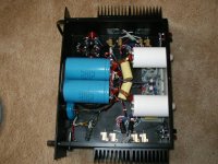
Jet-Mosfet cascode front end, Mosfet gain stage, Class A IXYS Mosfet output. No global feeback except for DC offset. Toshiba, Zetex,IR,and IXYS fets. Holco, Caddock, and Dale wire wound resistors, cardas jacks, silver clad telflon wire. Rifa, Spague 36D, and Panasonic caps. LC filtered seperate supply for front end.
H.H
Attachments
One Amp I made for a friend
Hi folks,
I hope attaching an image works.
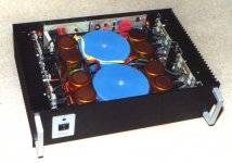
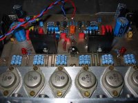
This is a rather big Amp I made for a friend. It can deliver 2*450 Watts at 4 Ohms if a fan is attached to the heatsinks.
It is a bridge Amp, intended for PA rather than for home, but it sounded surprisingly good.
Inside there are the bridging circuit, a symmetrical folded cascode gain stage, IRF540/9540 output FETs, softstart and security functions.
Not a high end project, but quite powerful.
At this time I am working on a more audiophile Amp with less power but more linearity and low noise.
Ciao and happy listening
Andy
Hi folks,
I hope attaching an image works.
This is a rather big Amp I made for a friend. It can deliver 2*450 Watts at 4 Ohms if a fan is attached to the heatsinks.
It is a bridge Amp, intended for PA rather than for home, but it sounded surprisingly good.
Inside there are the bridging circuit, a symmetrical folded cascode gain stage, IRF540/9540 output FETs, softstart and security functions.
Not a high end project, but quite powerful.
At this time I am working on a more audiophile Amp with less power but more linearity and low noise.
Ciao and happy listening
Andy
Attachments
Re: One Amp I made for a friend
Hey would u be kind enough to let me have a look at the schematic for one of the amp modules (not a bridged pair)? I built an amp using the IRF540/9540's (two pair per channel) and had a hard time getting crossover distortion eliminated without heavy bias -- too much bias for my likings. I eventally used more expensive MOSFETs.
Looks good!
AndyM said:Inside there are the bridging circuit, a symmetrical folded cascode gain stage, IRF540/9540 output FETs, softstart and security functions.
Andy
Hey would u be kind enough to let me have a look at the schematic for one of the amp modules (not a bridged pair)? I built an amp using the IRF540/9540's (two pair per channel) and had a hard time getting crossover distortion eliminated without heavy bias -- too much bias for my likings. I eventally used more expensive MOSFETs.
Looks good!
")
UrSv said:Fleming J P,
Do you know if it is the Alexander Amplifier or The End Amplifier featured in High Fidelity? I have the old issues and have though on many occasions about building them.
/UrSv
Neither I think. I know that they were designed by Mogens Meilvang Andersen and that it is his 3. generation amp. The article I saw in High Fidelity didn't show any schematics. As far as I remember the title was "køkkebords højtalere".
If you want, I can scan the schematics and post them.
Randy,
as for a PA Amp, distortion was not the main focus...
I chose the IRF-types because of their ruggedness.
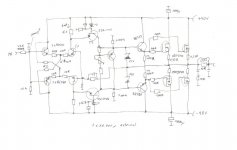
I will post the schematic tonite, because right now I am at work. I don´t have the original anymore, but I think I can reconstruct it.
Which FETs did you choose, because I want to use MOSFETS in my current project too? For this, distortion really is an issue.
Ciao
Andy
as for a PA Amp, distortion was not the main focus...
I chose the IRF-types because of their ruggedness.
I will post the schematic tonite, because right now I am at work. I don´t have the original anymore, but I think I can reconstruct it.
Which FETs did you choose, because I want to use MOSFETS in my current project too? For this, distortion really is an issue.
Ciao
Andy
my second amp
Hi all,
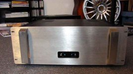
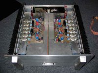
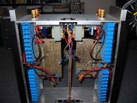
finally got my digital camera back so now I can post some pictures of the amp I´ve been modifiing and rebuilding for about 17 years. It´s based on the elektor Crescendo but with some different parts, regulated power supply (drivers only), dc-servo and 6 instead of 4 fets per channel.
Main power supply is two times 500VA transformer, discrete bridges and 100mF per channel. Power is 70watts/8 Ohm and 136 watts/4 Ohm. Bias is 1A, so up until about 16watt/ 8 ohm it´s class A going to AB after that.
The case is made out of 5mm aluminium, the front is 10mm thick.
william
Hi all,
finally got my digital camera back so now I can post some pictures of the amp I´ve been modifiing and rebuilding for about 17 years. It´s based on the elektor Crescendo but with some different parts, regulated power supply (drivers only), dc-servo and 6 instead of 4 fets per channel.
Main power supply is two times 500VA transformer, discrete bridges and 100mF per channel. Power is 70watts/8 Ohm and 136 watts/4 Ohm. Bias is 1A, so up until about 16watt/ 8 ohm it´s class A going to AB after that.
The case is made out of 5mm aluminium, the front is 10mm thick.
william
Attachments
another picture without the lid on shows the two main boards.
The bridges and transformers are below these (shielded), the compartment in the back hold the two transformers for the regulated supply and the 12V supply, softstart and fuses
The bridges and transformers are below these (shielded), the compartment in the back hold the two transformers for the regulated supply and the 12V supply, softstart and fuses
Attachments
- Status
- This old topic is closed. If you want to reopen this topic, contact a moderator using the "Report Post" button.
- Home
- Amplifiers
- Solid State
- I want to see your amps!