Good morning everybody!!
I've purchased a 2nd hand (damaged) Marantz PM-84 MkII for a few bucks.
(Hope one day I will own a PM-94") )
)
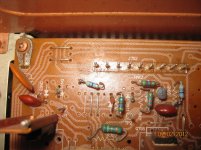
I've found the problem, as per picture under this line
My problem is I do not know values for adjusting new potentiometers... As you can see one of them has serious damages (R726)
I've found PM-84 SM (not MKII) but it is quiete different and less sophisticated
So, if anyone can provide me the right values (and the how-to) or else can provide me the whole SM for PM-84 Mk II I will acklowledge so much!!
I've purchased a 2nd hand (damaged) Marantz PM-84 MkII for a few bucks.
(Hope one day I will own a PM-94
)I've found the problem, as per picture under this line
An externally hosted image should be here but it was not working when we last tested it.
My problem is I do not know values for adjusting new potentiometers... As you can see one of them has serious damages (R726)
I've found PM-84 SM (not MKII) but it is quiete different and less sophisticated
So, if anyone can provide me the right values (and the how-to) or else can provide me the whole SM for PM-84 Mk II I will acklowledge so much!!
The trims nearby are 22K (223), with the Marantz switched off you could measure with a multimeter the R726 Trim to see if it too is 22K which is likely... problem solved. It looks to me that it has just lost its top, The plastic part just enables adjustment.. which means despite looking to be a problem it is probably reliably still working as a resistor. If you need to replace it, measure its range with a multimeter, trims like this are readily available in electronics shops.
If replacing or just measuring its range, note its present position and return it there which appears to be midway across its range. Check it with your multimeter and return it to its original position before reapplying power.
Cheers / Chris
If replacing or just measuring its range, note its present position and return it there which appears to be midway across its range. Check it with your multimeter and return it to its original position before reapplying power.
Cheers / Chris
Last edited:
Hello, ColdCut
All schems for PM-84 Mk II are welcoe. Now I need to start it but later probably I'll go further for some moods
Hello to @ll
After measurement, actual values are
R727 –> 3k12 ohms R728 –> 3k34 ohms
R725 –> 12k88 ohms R726 –> 12k98 ohms (damaged)
R723 –> 15k25 ohms R724 –> 15k54 ohms
I think I can trust adjust values as per this spare sheet I've found
And also I think values for R725 and R726 are too high; I guess must be around 7k5, 8k Ohms instead of almost 13k Ohm
By the way I consider this 'cause I've found 2 resistors dead of 150 Ohm each one, located on this area
I'll keep posting about
See you
All schems for PM-84 Mk II are welcoe. Now I need to start it but later probably I'll go further for some moods
Hello to @ll
After measurement, actual values are
R727 –> 3k12 ohms R728 –> 3k34 ohms
R725 –> 12k88 ohms R726 –> 12k98 ohms (damaged)
R723 –> 15k25 ohms R724 –> 15k54 ohms
I think I can trust adjust values as per this spare sheet I've found
An externally hosted image should be here but it was not working when we last tested it.
And also I think values for R725 and R726 are too high; I guess must be around 7k5, 8k Ohms instead of almost 13k Ohm
By the way I consider this 'cause I've found 2 resistors dead of 150 Ohm each one, located on this area
An externally hosted image should be here but it was not working when we last tested it.
I'll keep posting about
See you
Last edited:
HEEEEEEEEEEEELP
I have a doubt and I've stopped all intervention before clarifiying it
Before start the PM-82 for adjusting the pots (I will exchange the whole 8 for safety and longevity reasons)
- Do I have to put all them in value 0K or in value 22K ?
- And probably the most important thing, it is turning the adjustment screw clockwise on counter clockwise until its end?
Once decided this, as per previously attached info I will adjust them.
Many thanks
It might seem a good idea, Sr. Audio, but no.
Get it working with the one replacement first.
This may seem easy in thinking about it and for a technician it could be so but you
have no experience so please keep it simple and take things just one step at a time.
Fix just this one pot. and make sure it does work correctly first. They don't get moved in use, so there is no real point to replacing something that is not broken or worn.
You can replace whatever you like, of course but get this right first since none of this is yet certain.
Edit: You can assume that voltages of the controls increase clockwise. However, you took measurements and you can surely draw approximate positions.
The adjustments are for offset voltage (measured at the output terminals when the amplifier is on without speakers and also bias
current, measured across several marked test points TP1-8 at apparently 2 stages of bias. this is not so simple. so perform adjustments on one channel only so that you always have a reference.
Last edited:
oh, oh...
I'm the one who speaks fluent english (or I think so) but the soldering-iron man is a long pal of mine for several years...
He did remove all pots yesterday, I'm afraid.
So, now it is time to adjust. As per tested values, half of the pots have to be moved clockwise to reach "0" value and the other side counter clockwise.
So, for keeping a system we will follow the procedure shown on the PM-82 MkII service manual I found on the web by adjusting all 6 pots to "0" does it means turn top to left or top to the right, depending on the side.
The main idea "keep it as it was" for making work again sounds GREAT but then, why the resistors blow up?
My friend considers it is probably a result of trying to change values, taking a look to actual values of R725 and R726.
Today is 31/12/11 so probably until next weekend no adjusts are going to be done.
I hope someone with experience do explain we are on the right track for adjusting this.
By the way HAPPY NEW YEAR 2012 to you @ll
I'm the one who speaks fluent english (or I think so
) but the soldering-iron man is a long pal of mine for several years...An externally hosted image should be here but it was not working when we last tested it.
He did remove all pots yesterday, I'm afraid.
So, now it is time to adjust. As per tested values, half of the pots have to be moved clockwise to reach "0" value and the other side counter clockwise.
So, for keeping a system we will follow the procedure shown on the PM-82 MkII service manual I found on the web by adjusting all 6 pots to "0" does it means turn top to left or top to the right, depending on the side.
The main idea "keep it as it was" for making work again sounds GREAT but then, why the resistors blow up?
My friend considers it is probably a result of trying to change values, taking a look to actual values of R725 and R726.
Today is 31/12/11 so probably until next weekend no adjusts are going to be done.
I hope someone with experience do explain we are on the right track for adjusting this.
By the way HAPPY NEW YEAR 2012 to you @ll
same amplifier different problem
Dear all,
I would appriciate your help to my current problem with same amp PM84 mkII. One channel is faulty and I have tried to replace several FETs but without longtime success. Actualy it last for several hours and suddenly right channel burn. Friend of mine is better electrical technician and we follow all specifications with bias tunning and did lot research and we have replaced meny parts but unforthunatelly without final result.
Could someone help out of his experiance or give any advice in what direction we should go.
Other problem is that SM scheme that I downloaded is bit different to mine amplifier. Therefore I can not find type of zener diode DN09 and DN11 (visible on picture). Colud someone help with this issue?
Thanks in advance!
Best regards and many greetings from Croatia.
Goran
Attachments
- Home
- Amplifiers
- Solid State
- Some help or a SM for PM-84 MK II