I don't accept "always conducting" as a sufficient definition for ClassA operation.if the bias is such that the output devices are always conducting
There are many "cheat" ClassA, ClassAA etc circuits that deliberately hold the "OFF" device at a non zero current. and use this to claim they have a lower dissipation ClassA circuit.
the upper and lower devices of a ClassA PP stage must always actively control the output current. And further I think that the waveform variation of the current in the upper and lower devices must follow the audio waveform, for the output to be Real ClassA.
That last sentence is in effect telling us that as the doubled Ibias is approached the accuracy of the waveform following is dropping off and that the ClassA nature of the output is debatable. eg. KSA50 is baised to 1.9A. The peak output current is 3.8Apk just as one half of the devices are switching off.
I think that maximum ClassA applies to a slightly lesser output current. Maybe 3.7Apk or 3.62Apk or some other value that can be technically defined after some experimentation to prove when the accurate ClassA "actively controlling" starts to deviate from Real ClassA.
The JLH is not a conventional Push-Pull output stage.THe JLH is biased for half peak output current, and being pushpull this is a proper class A design.
It is nearer to a SE output stage with an active source/sink.
The clever bit is how that active source/sink is modulated to vary the bias.
Checklist:Hi Kenpeter, tried it and your idea works. It runs cold, only thing is the distortion is very much audible now. I tried different values of R which changes both the power dissipation and distortion. The higher the dissipation the less the distortion. When I say audible it is quite obvious, probably 5% or more (subjectively).
You are taking both output and feedback from midpoint of Schottkys?
You are taking bootstrap (if any) from the top emitter, not midpoint?
R1 sized to conduct more current than your bootstrap (if any)?
(R1 purpose to prevent bootstrap from shutting any transistor off)
You used only Silicon Schottky, not Silicon Carbide Schottky?
If feedback trace still goes directly to emitter (or collector) and not
the new midpoint, will definitely hear diode distort. Would believe a
.5% distortion, but 5% seems way much. Something simple might
have been missed...
Last edited:
I don't accept "always conducting" as a sufficient definition for ClassA operation.
Agree, and when I abuse such tricks, always want to be clear about it.
However, there is subtle difference between those that have no current
variation over half cycle and hard knee, and those that express smooth
complimentary curvatures over the majority of the full output swing.
R1 in my example was not purposed as an "always conducting" cheat.
Even though it is clearly exactly such a cheat...
But mostly there in-case you have to drive a bootstrap, not cause
curve of two Schottkys somehow knees over abruptly at quiescent.
Schottky quiescent (about 300~900mA) is hotter than hot AB, but
not hot as JLH (humped in the middle beyond even linear class A!).
Don't even need the extra 50~150mA that R1 provides to plausibly
call this class "Aa". If your JLH had no bootstrap, you could possibly
dispense with R1 entirely. But R1 also prevents reactive loads from
accidently shutting off a transistor, so I don't think this "cheat" is
anything bad.
"Aa + CCS" might be an accurate description of this class?
I've worked too hard to be lumped in with mere "AB + CCS".
So, not true class A, but then neither was our original JLH.
Can make linear class A by use of resistors instead of diodes,
but heat reduction from JLH to Linear A won't be as significant...
In 24V rails with 8 ohm load example, 50W is saved by restricting
JLH's enriched "aA" overcurvature down to Linear A. Another 50W
to be saved by restricting to Square Law vs Square Law class "Aa".
Last edited:
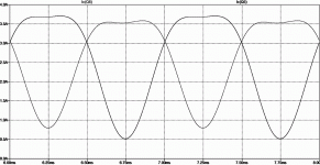
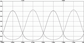
You can see the original JLH "aA" curves (bent due to 2n3055 beta droop)
equally as warped as Class "Aa" (bent due to Schottky diodes) . But there
is a waste of 100W difference between these classes.
Both of these might technically be Class A, and neither seems to cheat.
But neither of these curves should ever claim to be "Linear Class A".
The distinction Andrew's bitchin' about make plenty of sense.
Could say, "I'd never bias my JLH as hot as that first picture". But fact
of classic transistor droop, is that it will clip before reaching the rail if
you don't. Second pic allows plenty of generous bias to handle droop,
all the way to the rail, and discards any excess in the quiescent state.
Attachments
Last edited:
Quote: Originally Posted by toprepairman
THe JLH is biased for half peak output current, and being pushpull this is a proper class A design.
Unless you are using modern transistors, unchallenged by droop,
or accept an amp that clips before reaching the rail, I'd say not...
Low rail 10W versions maybe do not challenge 2n3055 droop?
High Watt JLH with classic transistors will see this challenge for sure.
If you bias for half "calculated peak" at quiescent, you will never have
enough bias to actually reach that peak. Beta droop devil gets you.
Last edited:
Hi Nico. Andrew is correct, regardless as to whether it is single ended or pushpull, if the bias is such that the output devices are always conducting (and not any strange sliding bias idea) then it is class A.
Who has been arguing? Me? Never said anything, all I say is KSA50 is over biased class B. Obviously you are only reading what you like...
THe JLH is biassed for half peak output current, and being pushpulll this is a proper class A design.
A single ended design has other considerations depending on whether it is choke/transformer coupled/loaded or resistive or constant current fed.
Okay so you know how class A works, single ended and push pull.
Last edited:
Checklist:
You are taking both output and feedback from midpoint of Schottkys?
You are taking bootstrap (if any) from the top emitter, not midpoint?
R1 sized to conduct more current than your bootstrap (if any)?
(R1 purpose to prevent bootstrap from shutting any transistor off)
You used only Silicon Schottky, not Silicon Carbide Schottky?
If feedback trace still goes directly to emitter (or collector) and not
the new midpoint, will definitely hear diode distort. Would believe a
.5% distortion, but 5% seems way much. Something simple might
have been missed...
Hi Kenpeter, yes did as you said. I also mention subjectively 5% since I can hear it, could be overstating it. Your idea works very well in fact as the dissipation very little at idle and increases as the signal increases. Very nice actually.
Kenpeter, found a lousy 6mm spade connection which caused very audible distortion. Since changing it, it is heaps better subjectively.
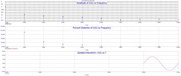
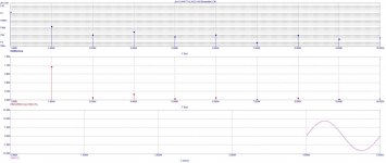
I simulated your modification and theoretically the modification increased THD by a factor of 8.
I think some attention to you proposal would be time well spent Kenpeter, this is just the right formula to introduce class A to the masses allowing them the opportunity ti hear real hi-fi at moderate cost
Attachments
Last edited:
Nico, if its running cool now: You can safely crank up your bias
until you clip 1V from either rail. A little bonus power! Though
I doubt the small distortion will completely go away, it should
not be audible.
I have obtained permission to use an Audio Precision at Texas
Instruments. That will tell us real world distortion. I just need
to get mine put back together well enough, so it can be moved.
Meticulous and neat as my professional work genuinely is, my
personal projects tend to look like Spaghetti monster exploded..
It may not be entirely conventional but it is pushpull. LJH even says so, and describes it, in the original wireless world article.The JLH is not a conventional Push-Pull output stage.
It is nearer to a SE output stage with an active source/sink.
The clever bit is how that active source/sink is modulated to vary the bias.
Hi Kenpeter, I cranked the bias up a little so the heat sink runs lukewarm and it sound pretty good too. I commend you on your great idea. It is time to kick this project in and I can now safely give this thing to the neighbour's hi-fi enthusiast 13 yr old kid to play with knowing he will not burn himself.
Hi Nico. Andrew is correct, regardless as to whether it is single ended or pushpull, if the bias is such that the output devices are always conducting (and not any strange sliding bias idea) then it is class A.
You could think of SRJLH a strange but simple "Sliding Current" bias.
to go with JLH's strange but simple "Current Steering" phase splitter.
I don't think a sliding bias, that also itself never shuts off, could or
should invalidate Class A? Why would it?
SRJLH was my attempt to introduce a simplest possible Quadrature
Feedback into the simplest possible amp that could benefit. If I get
complicated, I can make a "sliding voltage" conventional push pull
do exactly the same. Actively shaping output currents to whatever
bizarre misbehavior and output class my twisted mind might whim.
Every slider I've ever seen was , considering itself only , Class A .
You have to ask what curve the output devices were so shaped?
Yes, most sliders define Class AB curves, but not all of them do...
Last edited:
Hi Nico. Andrew is correct, regardless as to whether it is single ended or pushpull, if the bias is such that the output devices are always conducting (and not any strange sliding bias idea) then it is class A.
I never asked a question, I only stated that KSA50 was an over biased class B, that is it.
I do not know why you all think that I deserve an education, you obviously responded to display your own cleverness. Well done!
Hi Kenpeter, I cranked the bias up a little so the heat sink runs lukewarm and it sound pretty good too. I commend you on your great idea. It is time to kick this project in and I can now safely give this thing to the neighbour's hi-fi enthusiast 13 yr old kid to play with knowing he will not burn himself.
You did crank up the drive current bias (at your bootstrap or ccs),
not bypass current (R1)? Either would make the sink feel warmer.
But only the first makes the amp less likely to clip. I neglected to
be clear of which "bias" I was speaking in my earlier advice.
R1 only needs to be enough "bias" to work the bootstrap (if any),
and keep transistors ON if load gets reactive. But won't improve
anything but warmth in winter to crank this further...
I'm assuming since it sounds good, that you must have understood
and gotten it right? I'm just sayin' incase others are following, and
I don't think I remembered to specify to which bias I was referring...
Last edited:
and all I did was explain why I arrived at my opinion and why that disagreed with your opinion.I only stated that KSA50 was an over biased class B, that is it.
and all I did was explain why I arrived at my opinion and why that disagreed with your opinion.
I think it was all just miss-understandings. Lets forget about it, it is not really all that important. Sorry I got upset.
- Status
- This old topic is closed. If you want to reopen this topic, contact a moderator using the "Report Post" button.
- Home
- Amplifiers
- Solid State
- Need some help with Class A JLH power parameters