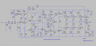
Here it is.
The statement in the schematic that reads "Replace R37 and R38 with a 2k precision trimmer" should read "Replace R37 and R38 with a 1k precision trimmer".
a few more graphs inorder
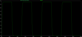
Strange way to do square wave test, only positive swing???
Strange way to do square wave test, only positive swing???
Hi Dadod,
Not so strange

kind regards,
Harrison.
Strange way to do square wave test, only positive swing???
Is it not? I mentioned it in his previous design.
I wonder how much heat the gate protection diodes on these output devices can take ?
Why? the device is rated at 150 degrees centigrade, it would be silly if they rated the diodes at any less.
Hi Dadod,
Not so strange
kind regards,
Harrison.
OK show us +- swing, or you don't know how to do that?
Use of the bias spreader with laterals is recommended because when trimer loses conntact there is no danger of possible distraction of laterals. Trimer should be connected between base and emitter and bias transistor should not be thermaly bonded with laterals.
dado
Why? the device is rated at 150 degrees centigrade, it would be silly if they rated the diodes at any less.
Hi Nico,
Thanks about the heat.
") Apologies for that meant wattage. Could they handle say 4 watts ?
Apologies for that meant wattage. Could they handle say 4 watts ? kind regards,
Harrison.
Hi Nico,
There is a thread in this forums that could explain that. I have lost track of it. With rail modulation the current isn't firmly held, thus the applied measures. The Goldmund clone features one of the sinks discussed there.
kind regards,
Harrison.
That could work. However I prefer this setup or a zener or string of diodes and it has noting to do with heat trackingWhy use a Vbe multiplier with Lateral Mosfets, that whole arrangement including precision pots can be replaced by a single resistor.
What are the purpose of D9 & D10, the double diode Vdrop will remain the same regardless of the additional noise introduced by the zener.
There is a thread in this forums that could explain that. I have lost track of it. With rail modulation the current isn't firmly held, thus the applied measures. The Goldmund clone features one of the sinks discussed there.
kind regards,
Harrison.
OK show us +- swing, or you don't know how to do that?
dado
Hi Dadod,
Could you show me
Hi Homemodder,
The first watt is the most important. Exactly what do our ears perceive ?
kind regards,
Harrison.
This amplifier isnt the one you think it is. With those FETs on the output, lets say its a different animal.OnAudio, why a new thread for this amp ??
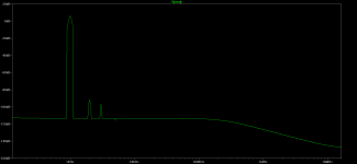
You should show THD and FFT s at higher powers than 1 watt, then things dont look so rosy anymore. Show a 10 or 20 volt swing so members can better compare to other designs on the forum.
The first watt is the most important
. Exactly what do our ears perceive ?kind regards,
Harrison.
Hi Nico,
That could work. However I prefer this setup or a zener or string of diodes and it has noting to do with heat tracking
There is a thread in this forums that could explain that. I have lost track of it. With rail modulation the current isn't firmly held, thus the applied measures. The Goldmund clone features one of the sinks discussed there.
kind regards,
Harrison.
Very likely it will not be held by a zener either. So your reasoning is hearsay?
Very likely it will not be held by a zener either. So your reasoning is hearsay?
Hi Nico,
Really
? How it works is that we take the first voltage. This voltage will have some variation, then we take a fraction of that variation by using a voltage divider. Resulting in better regulation.
How would you go about it ?
Kind regards,
Happy new year, hope your having a great time
Harrison.
Hi Raj,
Nice Job. I took a quick peek. I saw two pairs of mosfets instead of three. I found the ground slightly thin. The feedback looks ok to me since you took it from a stub.
I hope PCB domain experts will give their insights.
kind regards,
Harrison.
Hi Harrison,
Can it work with two pairs of mosfet? What maximum rail voltage to use?
I will alter the thin tracks accordingly.
Regards.
- Status
- This old topic is closed. If you want to reopen this topic, contact a moderator using the "Report Post" button.
- Home
- Amplifiers
- Solid State
- HAL SYMFET