Hello all, i really need guidance on this one. I have Rotel integrated amplifier from 80s. Symptoms (related or not I don't know) are: popping with membrane excursion upwards from both channels while pressing low filter button, same happens while turning bass knob, this symptoms are more pronounced in the first 2-3 minutes after power on. Second symptom is scratchiness in left channel while turning volume pot up or down, even if I move balance all way to the left I can still hear it, related to this (i think ) needle of VU-meter of the right channel declines itself from starting position on power up without music playing. Third symptom if I touch the chassis while no music is playing I can hear that in speakers. All of the above happens on all inputs independently is something is connected or not. I tracked all of the above symptoms to preamplifier, if I plug mp3 player in main amp in everything is fine, no popping no noise.
What I have done so far:
the unit was recapped last year (electrolytic caps only)
changed volume pot to sealed tkd
changed all transistors in tone board
changed C501,C502 ceramic 300pF to film caps
changed C545,C546 tantalums 3,3uf to electros
checked and re-soldered suspicious solder joints
My shotgun approach so far has not yielded any results and I am out of ideas and would appreciate any help. I took some voltage readings, default values in brackets E-C-B everywhere:
B+ (39,6) 41.1
B- (39,6) 41.1
voltage regulator Q904 (35.3-5?-35.9) 34-53,4-34,6 schematics shows collector voltage 5V, but I believe that is a typo, please confirm
Q506 (11.8-26.7-12.3) 11.1-26-11.6
Q505 (11.8-26.7-12.3) 11-26-11.4
Q504 (2.5-16.6-3.1) 2.8-13.9-3.4
Q503 (2.5-16.6-3.1) 2.9-13.2-3.5
Q502 (0.2-3.1-0.8) 0.2-3.4-0.8
Q501 (0.2-3.1-0.8) 0.2-3.5-0.8
Q508 (3.1-9.3-3.7) 2.8-10-3.4
Q507 (3.1-9.3-3.7) 2.8-10-3.4
I am running out of ideas and would appreciate all the help that i can get.
If better resolution schema is needed I will gladly upload it somewhere.
TIA
Attachments
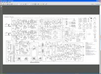
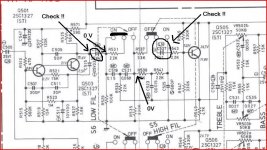
Try and put the file for the circuit in a zipped folder and post that. Too blurry to work from as it is")
Hi Mooly, here it is.
Attachments
Thanks for the circuit,
things to check with NO signal applied. And that is a typo on Q904.
As the amp has been recapped and worked on you need to make several checks.
There are three distinct stages in the preamp, a two transistor gain stage, a single emitter followe and a single stage incorporating the tone controls.
You need to measure from COLD and quickly the voltages on Q503/4 collectors.
The voltage on Q505/6 emitters.
The voltage on Q507/8 collectors.
Write down the results.
Now let the amp get fully hot and repeat the measurements. There should be virtually NO difference between cold and hot readings.
If pressing the low filter button causes a pop then that suggests DC is present across the switch terminals. It may well pop if there is a signal present.
So measure the voltage ACROSS the switch in the off position. It should be zero.
Be very careful making measurements as any short could damage power amp/speakers. Might be best to isolate power amp inputs while working on it.
I would suggest a grounding issue to the filter amp pcb. The schematic does not show where the ground to the board or to the volume control originates, only the connections E4 and E7. As I see it the only way to develop a voltage across the low filter switch is if the resistors from the coupling caps to ground (R529- R535) are not keeping the filter sides of the cap properly referenced to ground and the leakage across the caps (C517) could build up and cause a pop. R561 not grounded well could cause the same issue on the bass control. Electrolytics leak even when new. I remember equipment of this vintage supplying ground to the PC boards through the mounting screws and odd ball problems like this creaping in over time. Just a thought. Mike
You need to measure from COLD and quickly the voltages on Q503/4 collectors. COLD 12.8/13.5 WARM 13.2/13.8
The voltage on Q505/6 emitters. COLD 10.5/10.8 WARM 11/11
The voltage on Q507/8 collectors. COLD 9.4/10.1 WARM 10/10.1
Write down the results.
If pressing the low filter button causes a pop then that suggests DC is present across the switch terminals. It may well pop if there is a signal present.
So measure the voltage ACROSS the switch in the off position. It should be zero.
Switch has two rows with three pins in each row. Across each pins the voltage is zero.
@amptech
I kept old transistors, tantalums and ceramics.
@MikeBettinger
I have to pickup my child now I will check those resistors and get back to you.
I think certain time line of my (wrongdoings) is needed here. I recapped amplifier in February this year, since then it worked flawlessly until two weeks ago when old problem of popping while cold while pressing low filter turned up again, cold weather maybe
Then I opened the amp again and changed transistors (since I presumed they are most thermally sensitive of all components). Then those tantalums and then ceramic disk. I may be wrong but changing C501,C502 ceramic 300pF to film caps made the popping less intensive.
thank you all for helping me.
I would suggest a grounding issue to the filter amp pcb. The schematic does not show where the ground to the board or to the volume control originates, only the connections E4 and E7. As I see it the only way to develop a voltage across the low filter switch is if the resistors from the coupling caps to ground (R529- R535) are not keeping the filter sides of the cap properly referenced to ground and the leakage across the caps (C517) could build up and cause a pop. Mike
I took some measuring in circuit, I did not have the time for lifting one leg as my wife is baking cookies and that leaves only me to guard the kid but maybe this data will be of some importance. I took a picture of resistors in question and the fourth one (R550 4.7K) from the bottom looks like it has seen better days. Please comment as I don't have much experience with resistors, that hole on the third one (R546 330K) looks suspicious to me also, but I don't know.
R546(330K) 0.0162M
R550(4.7K) 4.7K suspicious one
R530(100K) 76K
R534(22K) 21K
R536(330) 77K
R540(10K) 9.88K
R542(22K) 21K
R529(100K) 76K
R533(22K) 21K
R535(330K) 77K
R539(10K) 9.91K
Attachments
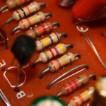
Thanks for the readings... they seem OK and don't show much all that much drift. Also I'm sure the resistors will be OK. Unless you just desolder one end with braid and at the sametime use a croc clip as a heat shunt on the leg you can end up making things worse.
The resistors are the very last suspects. They all look normal tbh, the "hole" is just the ceramic or whatever coating... not a problem.
Look at the circuit and the "top" channel.
Resistor R531 can either bypass the filter consisting of C519 and C521 when the switch is "off" or place those components in circuit when on. So measure the DC voltage across those two series caps from end to end. That is from the junction of C517/R531 and C521/R539. If that is not zero volts DC then you will get a thump as the switch is operated. All those points are referenced to ground via R529 and R539 so they should be truly at 0.000 vdc. Make sure there is no signal applied.
Thanks for the readings... they seem OK and don't show much all that much drift. Also I'm sure the resistors will be OK. Unless you just desolder one end with braid and at the sametime use a croc clip as a heat shunt on the leg you can end up making things worse.
The resistors are the very last suspects. They all look normal tbh, the "hole" is just the ceramic or whatever coating... not a problem.
Look at the circuit and the "top" channel.
Resistor R531 can either bypass the filter consisting of C519 and C521 when the switch is "off" or place those components in circuit when on. So measure the DC voltage across those two series caps from end to end. That is from the junction of C517/R531 and C521/R539. If that is not zero volts DC then you will get a thump as the switch is operated. All those points are referenced to ground via R529 and R539 so they should be truly at 0.000 vdc. Make sure there is no signal applied.
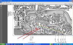
Mooly please don't thank me, you are helping me I am very grateful for that. I am enclosing picture which will reveal the magnitude of my ignorance in electronics and in art but please don't laugh at me.
red line 10.82V
yellow line 2.15V
green line 0.0V
blue 13.08V
Attachments
@amptech
I think certain time line of my (wrongdoings) is needed here. I recapped amplifier in February this year, since then it worked flawlessly until two weeks ago when old problem of popping while cold while pressing low filter turned up again, cold weather maybe
Then I opened the amp again and changed transistors (since I presumed they are most thermally sensitive of all components). Then those tantalums and then ceramic disk. I may be wrong but changing C501,C502 ceramic 300pF to film caps made the popping less intensive.
thank you all for helping me.
I agree that the resistors are the last to suspect. But the ground to the board being slightly bad, cold solder joint could possibly add a small potential and would account for the multiple symptoms as it is common to both the filtering and the bass control, also to both channels.
The image you posted was good but it is still hard to make out what is what and I assume by zooming out it will get harder to read. Measuring on the milivolt range of your meter using the main supply ground as your negative and the positive to the ground side of the resistors I mentioned see if you read anything. As Amptech pointed out it should be zero volts. Possibly during your first work you disturbed the connection and it started working, much like rocking a control back and forth to quiet it down. With time bad connections come back. Sometimes a can of freeze stray can help locate the culprit!
Mike
I have some new info that might be of relevance, I left the amplifier turned on over night and in the morning the right vu-meter needle was closer to zero, imagine my vu-meters have a scale from 0 to 10, immediately after powering on my left channel is on 1 and right on 3. In the morning left was on 0 and right on 1, and this time needles were jumping up with volume up or down with volume down (without any input). Looks like what ever DC is there it was lower after the amplifier was on for eight hours.
What is not very visible in the picture is that yellow, violet, red,gold 4.7K resistor has a slightly wrinkled, shrinked surface while other resistors in that row have almost a glossy surface, I would say the difference between them is like a skin from a 20-year old girl and from an old lady. It is also the only resistor that measured its nominal value in circuit, all other measured slightly lower value. Perhaps I should measure it from the underside, pcb side to exclude cold solder joint. Your suggestion is noninvasive, if I understand correctly one side of every resistor should read 0.0V relative to ground, main ground that would be E14?
I agree that the resistors are the last to suspect. But the ground to the board being slightly bad, cold solder joint could possibly add a small potential and would account for the multiple symptoms as it is common to both the filtering and the bass control, also to both channels.
The image you posted was good but it is still hard to make out what is what and I assume by zooming out it will get harder to read. Measuring on the milivolt range of your meter using the main supply ground as your negative and the positive to the ground side of the resistors I mentioned see if you read anything. As Amptech pointed out it should be zero volts. Possibly during your first work you disturbed the connection and it started working, much like rocking a control back and forth to quiet it down. With time bad connections come back. Sometimes a can of freeze stray can help locate the culprit!
Mike
What is not very visible in the picture is that yellow, violet, red,gold 4.7K resistor has a slightly wrinkled, shrinked surface while other resistors in that row have almost a glossy surface, I would say the difference between them is like a skin from a 20-year old girl and from an old lady. It is also the only resistor that measured its nominal value in circuit, all other measured slightly lower value. Perhaps I should measure it from the underside, pcb side to exclude cold solder joint. Your suggestion is noninvasive, if I understand correctly one side of every resistor should read 0.0V relative to ground, main ground that would be E14?
The VU meters are driven from the main speaker output via an opamp and rectifier. It's all AC coupled so the only way the meters can deflect is either because of a problem around the opamp stage or because the amp really is actually oscillating and is unstable and there really is an unwanted AC signal present.
You mention in post #1 that the amp has had quite a bit of work done to it. All these problems perhaps suggest something that has gone amiss during all the mods rather than a genuine "one off" fault.
You are going to have to work on this one stage at a time and it would be useful to also check the stability with a scope, however if you remove C635 and C636 feeding the VU meter stage then the meters should show zero at all times. If they do not and still drift and show various readings then that confirms a problem with the VU stage.
If removing the caps does cause the meters to read zero again correctly at all times then that points to instability in the amp somewhere.
The VU meters are driven from the main speaker output via an opamp and rectifier. It's all AC coupled so the only way the meters can deflect is either because of a problem around the opamp stage or because the amp really is actually oscillating and is unstable and there really is an unwanted AC signal present.
You mention in post #1 that the amp has had quite a bit of work done to it. All these problems perhaps suggest something that has gone amiss during all the mods rather than a genuine "one off" fault.
You are going to have to work on this one stage at a time and it would be useful to also check the stability with a scope, however if you remove C635 and C636 feeding the VU meter stage then the meters should show zero at all times. If they do not and still drift and show various readings then that confirms a problem with the VU stage.
If removing the caps does cause the meters to read zero again correctly at all times then that points to instability in the amp somewhere.
Hi Mooly and thank you,
you gave me a lot of work, I will try to do some of it if not all during this evening.
Now that you mention opamp I remembered while googling dc on volume pot I stumbled upon this page:
The Repair Bench: Carvin SX200 Guitar Amplifier | GuitarKitBuilder.com
"With our digital multimeter set for DC voltage we began to measure, beginning with the volume pot, and as suspected found about 13 volts DC on the pot terminals that connect with resistor R19. This voltage is pretty close to the power supply rail voltage, and in our experience should be no higher than a few tenths of a volt. Measuring further we found similar voltages on the output and inverting input (-) pins of op amp A1A. We found -14.2 volts on R17 at input of op amp A1A. Likewise the DC voltages on these pins would normally be no higher than a few tenths of a volt.
At this point we couldn't be sure whether the high voltage was coming from the op amp A1A, or from transistor Q2. To isolate the source of the voltage we de-soldered and lifted one lead of resistor R19. We found that the high DC voltage was now gone from the volume pot and transistor Q2, but still present on the op amp terminals. Our conclusion was that the op amp contained an internal short circuit, that was connecting the power supply voltage directly to the output and inverting input pins.
One verification of our diagnosis was that with resistor R19 lifted, we could now use the B-channel through input jack A/B without any hum or scratchiness.
We used our de-soldering tool to remove the A1 op amp, an NJM4558D chip, and ordered a replacement from Digi-Key. When the new part arrived it was soldered in place and the B-channel was found to work perfectly. Amplifier fixed, case closed.."
I have the same opamp NJM4558DD, any resemblance to my case?
Yours is a totally different design and application. Opamps are incredibly reliable providing that they are run withing their limits.
You must try it with those two caps disconnected to confirm the meters read zero at all times. If they don't then there is a problem with the VU circuit.
You must try it with those two caps disconnected to confirm the meters read zero at all times. If they don't then there is a problem with the VU circuit.
- Status
- This old topic is closed. If you want to reopen this topic, contact a moderator using the "Report Post" button.
- Home
- Amplifiers
- Solid State
- Help with DC on volume pot