Hi all.
I want to make an amplifier with high power like solid stage and also wanted it to sound natural like tube valves.
Remove components the output transformer to structure machine not too bulky.
ClassA output is quality but it is very hot,large heatsink,power supply many caps,...and expensive => I do not like.
I choose classAB,high quality + easy + inexpensive
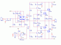
My project here.
I have designed circuit, not yet layout.
Everybody see have to change anything? if it's OK, I will layout.
Comments please.
Thank everybody.
Attachments
I like the topology and I'm quite confident it will sound very good.
Nice effort!
I would lower gain on the pentode a little to around 30dB overall; Av = 50 is a little high.
I would make the CCS more stable by using two voltage reference diodes and increasing R1 and R23 so current is around 12mA overall. Servo is good, well set up.
You should have source resistors on M3/M4, all around I would use 0.15R or 0.22R.
Instead of using D2/D3/Z1/Z2, I would simply use a single 4.7V zener across the two gates. This will confer adequate protection and is simpler.
You could replace the two pos and neg supplies on the tube with a single 250V positive B+ supply, and reference the cathodes and input grid to ground. This would be quieter.
Nice circuit, congratulations!
Hugh
nice design! I am a fan of hybrids  i've built several ones.
I agree with AKSA. For single HV supply, you can remove input cap.
I don't use it with this topology, even in my car-audio designs (lot of vibration) without any problem during the years
Make Av= 20-30. I often use 20 (but i use Mu-follower preamp)
You can lower the Mosfet's gate stopper. I use successfully 100ohm for N & P channel, without oscillation.
100mA output's idle current is great for Laterals
I agree with AKSA. For single HV supply, you can remove input cap.
I don't use it with this topology, even in my car-audio designs (lot of vibration) without any problem during the years
Make Av= 20-30. I often use 20 (but i use Mu-follower preamp)

You can lower the Mosfet's gate stopper. I use successfully 100ohm for N & P channel, without oscillation.
100mA output's idle current is great for Laterals
Thank everybody
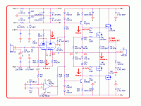
After receipt the comments of guys, I have these changes.
1. Add two diodes for CCS
2. Replace the OPA134 become AD706J
3. Reduce the gain for the first stage, only about 30 times
I remain symmetrical power supply for the first stage, because it's convenient for the rectifier (I'll use the double voltage circuit from AC main power supply)
Regards
Attachments
Last edited:
The symmetrical supply may be convenient, but it certainly is not optimum from several standpoints.. First it requires an additional coupling cap, and the negative supply is a convenient point to inject additional noise into the driver circuitry, in addition there is another set of caps in the audio path tying the negative rail to the audio ground. Just remember to reference the filament supply to something close to the negative rail. I suspect that rather than the nice controlled warm up behavior you would get with the single supply you are going to get a very large negative transient at the output at power on and this will necessitate a muting relay that might not otherwise be necessary.
One other comment involves the linearity of the driver circuit, with bias of just 340mV the maximum linear swing at the plate is going to be pretty limited - perhaps significantly less than 20Vpp. The bias needs to be significantly greater than the input voltage required to achieve your output power goal - which also means you may need to select a different tube or run the pentode section (triode connection is not helping here) at higher current. (Tubes used in amps with significant OLG with lots of global feedback applied only amplify the difference between the input and feedback signal (error signal) - this is not the case when running without global feedback - hence their signal handling is quite limited, and you need to choose something more suitable - for example something like the 6SN7 or 6H30P would probably do a much better job here.)
One other comment involves the linearity of the driver circuit, with bias of just 340mV the maximum linear swing at the plate is going to be pretty limited - perhaps significantly less than 20Vpp. The bias needs to be significantly greater than the input voltage required to achieve your output power goal - which also means you may need to select a different tube or run the pentode section (triode connection is not helping here) at higher current. (Tubes used in amps with significant OLG with lots of global feedback applied only amplify the difference between the input and feedback signal (error signal) - this is not the case when running without global feedback - hence their signal handling is quite limited, and you need to choose something more suitable - for example something like the 6SN7 or 6H30P would probably do a much better job here.)
You right,The symmetrical supply may be convenient, but it certainly is not optimum from several standpoints.. First it requires an additional coupling cap, and the negative supply is a convenient point to inject additional noise into the driver circuitry, in addition there is another set of caps in the audio path tying the negative rail to the audio ground. Just remember to reference the filament supply to something close to the negative rail. I suspect that rather than the nice controlled warm up behavior you would get with the single supply you are going to get a very large negative transient at the output at power on and this will necessitate a muting relay that might not otherwise be necessary.
I will reconsider this problem,I can changes
Please more comments,everything else.
I until not yet layout.
I am waiting everyone finished comments,I will layout and share PCB for all
Thank all.
...
One other comment involves the linearity of the driver circuit, with bias of just 340mV the maximum linear swing at the plate is going to be pretty limited - perhaps significantly less than 20Vpp. The bias needs to be significantly greater than the input voltage required to achieve your output power goal - which also means you may need to select a different tube or run the pentode section (triode connection is not helping here) at higher current. (Tubes used in amps with significant OLG with lots of global feedback applied only amplify the difference between the input and feedback signal (error signal) - this is not the case when running without global feedback - hence their signal handling is quite limited, and you need to choose something more suitable - for example something like the 6SN7 or 6H30P would probably do a much better job here.)
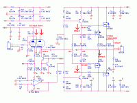
Beginning I chose tube 6AN8 but now it is difficult find,not multiple. I chose tube similar is 6U8A by popular,natural sound similar to 6AN8/7199 /,... I've heard.
I liked the sound of rustic, natural, not too sharp, ...should 6AN8 is choice suitable in my opinion.
The problem output impedance in first stage,I was overcome by cathode output,Z output only 4760R.
Input impedance solid stage very large,in high frequency lateral mofet needed more current to win parasitic capacitors inside the mosfet,and 3mA is enough to do it.
The problem of non feedback global,I want to so,If have many feedback the sound not natural,heard the same as solid amplifier
Of course the cost is output high impedance,low damping factor,...I parallel two lateral mosfets because it.
Regards,
Last edited:
I like it, except for the driver I would use beefier tube, with idle current round 30 mA, common cathode, loaded on MOSFET gyrator.
Something like on the picture in the first post in this thread:
http://www.diyaudio.com/forums/tubes-valves/147916-wavebourn-tower-iii-high-end-hybrid-amp.html
Something like on the picture in the first post in this thread:
http://www.diyaudio.com/forums/tubes-valves/147916-wavebourn-tower-iii-high-end-hybrid-amp.html
I like it, except for the driver I would use beefier tube, with idle current round 30 mA, common cathode, loaded on MOSFET gyrator.
Something like on the picture in the first post in this thread:
http://www.diyaudio.com/forums/tubes-valves/147916-wavebourn-tower-iii-high-end-hybrid-amp.html
My circuit has the advantage that greater capacity,input impedance solid stage very larger.
ClassA,I also like but larger capacity is too expensive, too bulky,...
Regards,
My circuit has the advantage that greater capacity,input impedance solid stage very larger.
ClassA,I also like but larger capacity is too expensive, too bulky,...
,
I did not mean class A, I meant driver with more voltage swing and current capability.
Yes, on DC FET followers have huge input resistance, but on AC they are devices controlled by charges, so have input capacitances, though bootstrapped, but anyway speaker load is reflected on them.
You've asked for suggestions, so I suggested...
Sorry,I do not watch carefully,it is not classA.
I'll option more the feedback global circuit to have more choice for someone like it.
If so,I will choice first stage is pentode to up gain,feedback global
Please you comment.
Regard,
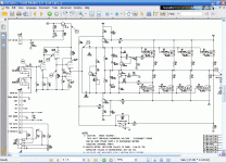
Similar SS stuff
This circuit is the same as the SVT bass amp.
I had a customer bring in one of these monsters and I was surprised at the clever way the circuit gets around a phase inverter or "driver" stage by using opposite polarity Mos-fets.
I would lower the kathode resistor on the 6u8 to 12K and up the watts on the triode, as lower impedance drive to the mos-fets
Also, you could use a 6FM7, and run the power triode at up to 10 watts idel, for massive drive power. I have used these tubes as line amps and headphone amps, with the power triode at 7.6 watts idle. They have a very big tone compared to 9-pinny tube.
You could also use a interstage transformer to drive the mosFets and get a nice coil tone, without the big iron.
Then use try-odes to drive the tranny, and the tranny to drive the mos-fets
gEo
Where I am living have not DN2540,it is easy to replaced by BJTyou can use DN2540 (or the IXYS 10M45) for the tube buffer's CCS
Less components, better performance
Sonically, i prefer these kind of amp without global feedback
I choose KSE340 and MPSA42 are found everywhere.
If not like FB, can remove R17,not use it.
Regrads
- Status
- This old topic is closed. If you want to reopen this topic, contact a moderator using the "Report Post" button.
- Home
- Amplifiers
- Solid State
- New Project - Hybrid Amplifier High Quality


