Hi guys,
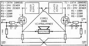
I want to show you this simple Circlotron circuit. In the simulation with LT-Spice it works very well. The signal will be taken off from this circuit at the drain of the MOSFET. It is therefore a flawless transconductance amplifier.
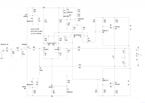
This is the circuit diagram:
This is the FFT simulation:
These are the frequency responses, open loop an closed loop.
Ready to play")
I want to show you this simple Circlotron circuit. In the simulation with LT-Spice it works very well. The signal will be taken off from this circuit at the drain of the MOSFET. It is therefore a flawless transconductance amplifier.
This is the circuit diagram:
An externally hosted image should be here but it was not working when we last tested it.
This is the FFT simulation:
An externally hosted image should be here but it was not working when we last tested it.
These are the frequency responses, open loop an closed loop.
An externally hosted image should be here but it was not working when we last tested it.
Ready to play
I have simulated a little bit.
And I found out that the current availability is extremely important in this topology. With the 2SK1058 the distortions increase sharply at higher powers. The IRFP240 provide significantly better results.
Now I know why Thorenz use in their Circlotron such strong mosfets.
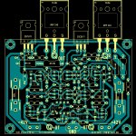
Now I'll build this circuit to test:
And I found out that the current availability is extremely important in this topology. With the 2SK1058 the distortions increase sharply at higher powers. The IRFP240 provide significantly better results.
Now I know why Thorenz use in their Circlotron such strong mosfets.
Now I'll build this circuit to test:
An externally hosted image should be here but it was not working when we last tested it.
If possible avoid input opamp, better use double j-fet unity gain buffer, IMHO it is much more transparent than OPA604.
Perhaps, but as a prototype, it is easier and I get a good distance DC.
1kohm is very low, can a JFET buffer drive it with low distortion?
Yes, but a simple fuse enough for now.Keep in mind some fusing in the load???
Very nice!
Hi moschfet,
Nice to see that driver stage connection getting some use. It works quite well in practice; I've had similar designs running for some time (see US patent 6747513). You can easily drive it from a single differential voltage gain stage, if you like.
Also, as you probably know, the idle currents in the IRFP240 output MOSFETs will tend to increase as they warm up over time. If you provide compensation for that, you may not need source resistors in the output stage.
Best of luck with your design!
Joe
Hi Alex,
very nice.
I have seen your layouts and I like them very much, but you are too fast.
I have changed some details. I think the Mosfets must be thermally coupled with the current source Q10. So I plan to put Q11 on the heatsink. R17 is a pot to set the bias. I estimate, the circuit at the bias must be tuned in reality.
Attachments
Re: DC Offset
The DC offset problem noted earlier can be addressed by adding a current path from each output terminal to the -50V rail, to recapture the current supplied by Q10 from the +50V rail. Resistors will work, but an NPN current sink can be made to provide thermal tracking against the Q10 current source (though such precision may not be needed), and will better isolate the outputs from any noise on the -50V supply rail.
Also, speaking of 50V supply rails, I notice that the front end does not need nearly this much voltage to operate. It should work fine on 25V rails, or perhaps less.
That will probably work, but that's too complicated ... I will see later.The DC offset problem noted earlier can be addressed by adding a current path from each output terminal to the -50V rail, to recapture the current supplied by Q10 from the +50V rail. Resistors will work, but an NPN current sink can be made to provide thermal tracking against the Q10 current source (though such precision may not be needed), and will better isolate the outputs from any noise on the -50V supply rail.
Yes, I know, but I thought (and simulated) the amp produce less distortions with higher supply voltages.Also, speaking of 50V supply rails, I notice that the front end does not need nearly this much voltage to operate. It should work fine on 25V rails, or perhaps less.
Now I simulate something different
THD is now as well as before, there were the dog bury on an other place
I have simulated with +/-20V for the driver.
It is steadily improving
Sorry for the additional complexity. In exchange, I will offer a simplification.
Now that you have reduced the front end rail voltages, you can easily replace the input BJT array with a pair of N channel JFETs. Then, if you can live with a 10K ohm input impedance, you can increase the values of all feedback resistors by 10x, and remove the input buffer.
Now that you have reduced the front end rail voltages, you can easily replace the input BJT array with a pair of N channel JFETs. Then, if you can live with a 10K ohm input impedance, you can increase the values of all feedback resistors by 10x, and remove the input buffer.
Thank you for your forbearanceSorry for the additional complexity. In exchange, I will offer a simplification.
This is a version for fet-lovers and it works also with low distortions
An externally hosted image should be here but it was not working when we last tested it.
R23 is a pot for offset.
Yes, also nice Mosfets, but I would prefer the SIC-power-jfets from semisouth when I would build a high-end-version.
http://semisouth.com/wp-content/uploads/2011/05/DS_SJEP120R063A_rev1.1.pdf
http://semisouth.com/wp-content/uploads/2011/05/DS_SJEP120R063A_rev1.1.pdf
This is a version for fet-lovers and it works also with low distortions
Super, very nice.
Which version you will realize in near future?
Re: DC Offset
Yes, but let's be clear that what you are adjusting is the relative DC offset across the output terminals. There is still absolute DC offset voltage between each output and ground due to the front end return current through the 1K resistors. You don't have to correct it, but prospective builders should understand it so they know how the circuit will normally behave.
R23 is a pot for offset.
Yes, but let's be clear that what you are adjusting is the relative DC offset across the output terminals. There is still absolute DC offset voltage between each output and ground due to the front end return current through the 1K resistors. You don't have to correct it, but prospective builders should understand it so they know how the circuit will normally behave.
- Status
- This old topic is closed. If you want to reopen this topic, contact a moderator using the "Report Post" button.
- Home
- Amplifiers
- Solid State
- Simple Circlotron with power Mosfets