schematic on page 174
Indeed, the voltage difference between input and output is lower, but the THD, according to my sim, has increased four times. Where did you get this piece of xxxx from? Is this design from Acoustic Research? Hardly to believe.
Cheers,
E.
May be this one is better than old version of non feedback pioneer's, 0.1V drop voltage for normally 1V drop without it, no feedback (input compared FB).
Found it at AR D400 and may be solution I don't really know for this. I search for any patents and negative.
Indeed, the voltage difference between input and output is lower, but the THD, according to my sim, has increased four times. Where did you get this piece of xxxx from? Is this design from Acoustic Research? Hardly to believe.
Cheers,
E.
May be not the first seen at AR D400 and may be followed by soulution 710, no, not Accoustic Research, but Audio Research D200-400, $5K amp, and soulution 700/710, $45K amp. Both no feedback at OPS.
It need to be tuned for each OPS type, after tuning it still has minor load dependent and litle thermal dependent (that could be coupled) characteristics, but major crossover distortion is canceled.
Here for smoother canceling with more diode arrangement.
5ppm @10kHz
It need to be tuned for each OPS type, after tuning it still has minor load dependent and litle thermal dependent (that could be coupled) characteristics, but major crossover distortion is canceled.
Here for smoother canceling with more diode arrangement.
5ppm @10kHz
Attachments
10kHz
9ppm@30ohm
6ppm@20ohm
4ppm@16ohm
5ppm@12ohm (I do tune it here)
8ppm@10ohm
15ppm@8ohm
20ppm@6ohm
25ppm@5ohm
30ppm@4ohm
1kHz
9ppm@30ohm
6ppm@20ohm
4ppm@16ohm
5ppm@12ohm
8ppm@10ohm
10ppm@8ohm
17ppm@6ohm
20ppm@5ohm
25ppm@4ohm
THD OPS alone is ~1/30 as 30dB NFB applied. 0.013% @12ohm
It need to be enriched like what soulution do, high bias, but I still used 240mA. It also doesn't need to be enriched if drop EC (like hawksford's) is applied.
I don't know what soulution do there, but they get very low THD without feedback, my sims still 30dB NFB.
9ppm@30ohm
6ppm@20ohm
4ppm@16ohm
5ppm@12ohm (I do tune it here)
8ppm@10ohm
15ppm@8ohm
20ppm@6ohm
25ppm@5ohm
30ppm@4ohm
1kHz
9ppm@30ohm
6ppm@20ohm
4ppm@16ohm
5ppm@12ohm
8ppm@10ohm
10ppm@8ohm
17ppm@6ohm
20ppm@5ohm
25ppm@4ohm
THD OPS alone is ~1/30 as 30dB NFB applied. 0.013% @12ohm
It need to be enriched like what soulution do, high bias, but I still used 240mA. It also doesn't need to be enriched if drop EC (like hawksford's) is applied.
I don't know what soulution do there, but they get very low THD without feedback, my sims still 30dB NFB.
Last edited:
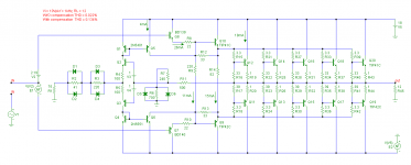
Most likely the PA0016 IC is based on this patent: Push-pull amplifier
However, this patent contains a serious error: the connection between node 'P' and 'out' gives an enormous amount of distortion. This is because it violates the 'crosswise connection rule'. Why does Pioneer apply for such a patent? To mislead the competitors?
In the meantime I've tried to reverse-engineer this chip, see 2nd picture. This one does a reasonable job.
(notice the multiplier m=7 !)
Cheers,
E.
edit: @ homemodder, our posts just crossed.")
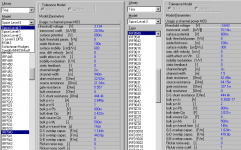
the model given Pioneer A-77X I replaced PA0016 in felu following:
An externally hosted image should be here but it was not working when we last tested it.
[...]
THD OPS alone is ~1/30 as 30dB NFB applied. 0.013% @12ohm
It need to be enriched like what solution do, high bias, but I still used 240mA. It also doesn't need to be enriched if drop EC (like hawksford's) is applied.
I don't know what solution do there, but they get very low THD without feedback, my sims still 30dB NFB.
I got a much higher distortion. Would you be so kind to give me the models, please?
Cheers,
E.
I am using all original models from TI7.
Here is the simulation files, of two not enriched and enriched. (it is rar, but can't upload so I just change the extension to .zip)
Simulator is TINA7, free downloadable from texas instrument site. but now there is different version that only for educational.
Here for ver7, in the past it is free from TI site as starter version: tina-ti_version_7-0_program_installation-use_for_initial_installation-g.exe - 4shared.com - online file sharing and storage - download
Attachments
AR D400
Hi Ontoaba,
Thanks for the files. However, I've tried to extract the models (in order to use them with MicroCap), but failed. So I downloaded them from the web (generated by MODPEX).
I got almost the same DC currents, though THD figures were not encouraging. With several loads from 4 to 32 Ohms, in all cases the distortion gets worse when the error cancellation circuit is enabled.
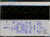
Below some pics:
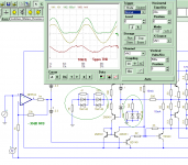
1. Schematic, Vout = 10V, f = 1kHz, RL = 12 Ohms
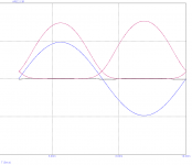
2. Some signals with cancellation circuit disabled. THD = 0.022%
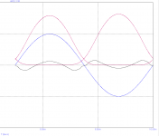
3. Some signals with cancellation circuit enabled. THD = 0.134%
Blue = Vout
Red = emitter current output devices.
Black = Residual.
Cheers,
E.
Hi Ontoaba,
Thanks for the files. However, I've tried to extract the models (in order to use them with MicroCap), but failed. So I downloaded them from the web (generated by MODPEX).
I got almost the same DC currents, though THD figures were not encouraging. With several loads from 4 to 32 Ohms, in all cases the distortion gets worse when the error cancellation circuit is enabled.
Below some pics:
1. Schematic, Vout = 10V, f = 1kHz, RL = 12 Ohms
2. Some signals with cancellation circuit disabled. THD = 0.022%
3. Some signals with cancellation circuit enabled. THD = 0.134%
Blue = Vout
Red = emitter current output devices.
Black = Residual.
Cheers,
E.
Attachments
Last edited:
models
Hi Ontoaba
please show your IRF540/9540 models, if you can
thank you in advance!
I am using all original models ...[/url]
Hi Ontoaba
please show your IRF540/9540 models, if you can
thank you in advance!
Inverting seems possible too, but this example has problems.
Poor bandwidth, gain, linearity, DC offset, and several diodes
needed for latch-up protection omitted for sake of clarity.
But maybe it a starting place for someone else to figure a
more workable solution. Or not...
I submit the concept for entertainment value only.
Poor bandwidth, gain, linearity, DC offset, and several diodes
needed for latch-up protection omitted for sake of clarity.
But maybe it a starting place for someone else to figure a
more workable solution. Or not...
I submit the concept for entertainment value only.
Attachments

@ Edmond
It need to be tweaked until drop voltage closest to sinewave. May be there is some differences in models, like 1N4148.
tina 4148: IS=1n, N=1.7, VJ=750m, MJ=330m, EG=1.11
@padamiecki
It is attached, but using spice level 3. A bit and more different, with level 1 that used in LTspice, but it is more accurate.
@kenpeter
Thanks for the concept, yes less quick in response and less stable but has better gain loop.
Attachments
@ Edmond
It need to be tweaked until drop voltage closest to sinewave. May be there is some differences in models, like 1N4148.
tina 4148: IS=1n, N=1.7, VJ=750m, MJ=330m, EG=1.11
[...]
Hi Ontoaba,
I have tried the 'Tina' diode, but to avail. Frankly speaking, if the compensations depends that much on model parameters, I don't think that the way to go.
Cheers,
E.
Also known as h bridge ???
How about AD8047 ?? Another reference could be analog devices MT-056 tutorial, theres a patent too but Id have to look it up again.
Hi Homemodder,
Oh, now I see what you mean by 'quad core'. The Stochino amp has a quad-core input stage.
Please look here: http://www.diyaudio.com/forums/solid-state/196527-high-slew-rate-design-time-forgot.html#post2709418
Cheers,
E.
H-bridge
>I dont think it quite operates like the quad cores thou
Have a look at the R and C that 'bridge' the two tales together.
Also look here for another way to linearize the IPS:
http://www.diyaudio.com/forums/soli...-blowtorch-preamplifier-1957.html#post1855285
and here:
http://www.diyaudio.com/forums/soli...-blowtorch-preamplifier-1957.html#post1855494
Cheers,
E.
Hi Edmond. I'm posting this for curiosity, I don't know how much it falls in the realm of so-called "improvements".
I simulated your ABII circuit with VN22xx/VP22xx driving C5200/A1943 (the FJP models from Fairchild are actually better than all the other models). I discovered that matching the Cgs of the complementary drivers caused their capacitive currents to cancel, partially. This current arising from the rectified half-sine base current of the output BJTs. Perhaps the remaining bump is a residual of gm-doubling appearing across C2/C3, and badly summing base currents.
I found the lowest distortion when the current through Q3 and Q4 (my schematic) was lowest (this may be for the non-cross-collector version). The lower current used in these transistors the more accurate the CCS and tempco stuff had to be, and of course it was an "approaching zero" thing. I had the idea of using the class-I circuit outside of a feedback loop, maybe as a bench audio-purpose buffer if not for listening.
When messing with my K-multipliers, I found the BC550C/560C to have the best low-Vce behavior (about 1.3V Vce), better than anything else I had access to. I recently found the BC327-25/337-25 (BC807/817) to be better, maybe the lower Hfe class would also be an improvement. In any rate I think quasi-saturation may be important here, it may screw everything up and it is not modeled in the simulator. I think small NXP BISS transistors may be good here, like the PEMZ7 and it's cousins (dual packages available). It should work really well at low-Vce. 15V max Vce, so horses for courses. It's like the 2N5769/5771.
Would it be beneficial to seek out BJTs designed for good log conformance?
Attachments
- Status
- This old topic is closed. If you want to reopen this topic, contact a moderator using the "Report Post" button.
- Home
- Amplifiers
- Solid State
- Class i and siblings