auto-censor
I get a bit excited at times and think that I am actually funny when it was the Auto-Robot-Censor that cracked the joke. Strike me pink, I'm getting too old for this stuff.
Bring back the horse and cart.
If you miss-type "assess" the auto censor obliterates the word. Not at all helpful.
I get a bit excited at times and think that I am actually funny when it was the Auto-Robot-Censor that cracked the joke. Strike me pink, I'm getting too old for this stuff.
Bring back the horse and cart.
That's pretty good humour!
I can get a bit cantankerous at times Ken but I must say that is a good one.
I can remember a bloke from Eugenana named Knuck, he brewed the stuff and my uncle introduced my mum to it one christmas and she laughed and then had a big long sleep - this is the only time I have ever seen Ma intoxicated, and that was funny!
When I first read the name 'Samuel Smith' I thought he was another electronics guru and wanted to find out a bit more of his philosophy on A-Class amps. Excellent.
Bye for now.
About 4 pints of Samuel Smith...
I can get a bit cantankerous at times Ken but I must say that is a good one.
I can remember a bloke from Eugenana named Knuck, he brewed the stuff and my uncle introduced my mum to it one christmas and she laughed and then had a big long sleep - this is the only time I have ever seen Ma intoxicated, and that was funny!
When I first read the name 'Samuel Smith' I thought he was another electronics guru and wanted to find out a bit more of his philosophy on A-Class amps. Excellent.
Bye for now.
Progress
I have adapted the silicon chip amp to save some time as I am building a few speaker enclosures at the moment.
These class A (or A/B) amps are pretty simple, in terms of their build and I would suggest it is a good place for a beginner to get started into solid state amps. Buy a kit from a reputable supplier and stick the bits into the holes - you wont be dissapointed if you follow the instructions supplied.
Design concepts are another thing altogether, and the SC amp bears little resemblance to the previously posted schematic - however I guess that the component count would be smaller on the SC than the Douglas Self original.
The board that I have cooked up is almost the same as the SC job with the exception of the output filter and power resistors, but so far so good.
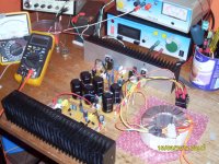
Here are a few of the changes I have made and my observations of the rig so far:
Here is a picture of the amp sitting on my bench.
Cheers, and bye for now.
I have adapted the silicon chip amp to save some time as I am building a few speaker enclosures at the moment.
These class A (or A/B) amps are pretty simple, in terms of their build and I would suggest it is a good place for a beginner to get started into solid state amps. Buy a kit from a reputable supplier and stick the bits into the holes - you wont be dissapointed if you follow the instructions supplied.
Design concepts are another thing altogether, and the SC amp bears little resemblance to the previously posted schematic - however I guess that the component count would be smaller on the SC than the Douglas Self original.
The board that I have cooked up is almost the same as the SC job with the exception of the output filter and power resistors, but so far so good.
Here are a few of the changes I have made and my observations of the rig so far:
- I have used a 300VA trannie because I had one.
- I have used the San Ken 2SC4468 & 2SA1695 transistors salvaged from the 'hummingbird'. According to the datasheet these will be adequate. Time will tell.
- Iq is set at 1.2A
- Even with the cheapest BC546/56 China sourced small signal transistors and some 5% resistors from the same supplier, the DC offset at startup was about 15mA for one and 5mA for the other board. I wont mess with that for now.
- One interesting thing is that the Q current decreases as the sinks take up the heat - which is moderate at the sink after 30min - the casings of the output transistors (front just below the screw) is about 75degrees and the sinks are 50 degrees C at their hottest point just behind the output device. This was measured using a cheap probe on my multimeter blu-tacked to the hot spots.
- Voltage across the output resistors starts at 264mA at start-up and decreases to 255mA after about five minutes.
- I have run the amps into 8 Ohm speakers using a sweep of audio frequencies 1v p2p in sine, tri and square wave and I experienced nothing unexpected although the square wave did have a small whisker at the top of its rising edge in some places.
Here is a picture of the amp sitting on my bench.
Cheers, and bye for now.
Attachments
It looks like a winner in the finishing there.
With reference to (4) I guess you mean mV offset which, of course, you can null by matching Vbe of the input pair and (according to some) this will improve the sound and add 20 years to your life as well. Just how you improve on vanishingly low distortion has me more than a bit puzzled but there you go.
What rail voltage do you have there? 24V or so?
Anyway 'looking forward to your final tests and good luck.
- Status
- This old topic is closed. If you want to reopen this topic, contact a moderator using the "Report Post" button.