It's only +/-115V. Those rails don't add, it just runs off whichever one is needed. Real world power with +/-115 rails goes from a low of about 650W/4R with a typical undersized toroid (RMX2450, EP2500) to about 1200W/4R with a solid regulated switcher in something more expensive. Maybe 2k-2.5k per side at 2R, but only for a short time. These amps only use between 4 and 6 pairs of outputs per channel.
The most powerful (PA audio) amps available, anywhere, only use +/-195V rails - they're limited by the devices available. It's 6.5kW per side at 2R, class TD and costs more than anyone here makes in a month. I'm pretty sure that supply is stiffly regulated to get that - put it on a soft AC line on a 20A circuit and you won't even approach that.
The most powerful (PA audio) amps available, anywhere, only use +/-195V rails - they're limited by the devices available. It's 6.5kW per side at 2R, class TD and costs more than anyone here makes in a month. I'm pretty sure that supply is stiffly regulated to get that - put it on a soft AC line on a 20A circuit and you won't even approach that.
I saw something like that before. Ancient shaker table driver, I can't almost remember the manufacturer's name... Occupied four solid racks, between the cooling, frequency generation, acceleration calibration and amplifier. Table itself was in another room, supposedly about a 1 ohm, 10kW overgrown subwoofer.
In the back of the amplifier rack, there were two water-cooled rails, each with around 50 stud-type bipolar transistors mounted. Amazingly enough, the design was a 50V, class AB circlotron! As you might guess from six linear feet of transistors, it was poorly compensated and exhibited parasitic oscillations during some portions of the cycle.
Oh yeah, remembered who made it, Unholtz Dickie. Looks like they're still making them, although I'm slightly bemused that most of their pictures are renderings. Their modern-ish switching amps are "only" 90% efficient, but that's a step up from their "older, water-cooled vacuum tube" amplifiers. I can guess what their business is like -- small production, high price, low development. I'd be surprised if they have a team of engineers designing these things, or for that matter, if the guys who did it are still around.
Tim
Awwwww
") ???????
???????
I am a commercial audio amplifying design engineer and want to know how in the hell you get 6kw with those parametersWhoops
???????Just to explore this rail switching philosophy.
The amp is set up and biased and output offset set to near zero when the lowest voltage supply rails are operating.
A good compensation scheme will keep the output bias and output offset under some form of controlled limits to ensure the amp performs on these low voltage supply rails.
Let's increase the the supply rails to the maximum to accomodate a high level transient.
Will the controls that governed output bias and output offset be able to keep those variables within the limits that applied when only the lowest voltage rails wer operating.
Particularly, consider the output offset. If this offset momentarily diverges from the quiescent value when the high voltage rails switch in, will the changed offset plus the transient combine into an indistinguishable "signal" that gets passed to the speaker and thus be heard as a form of added distortion?
BTW,
just in case any think I am bashing switchable rails. I think a similar questioning of variable or swinging bias in ClassA amplifiers to find if that changing set of bias and offset can distort the wanted transient signal.
Last edited:
I am a commercial audio amplifying design engineer and want to know how in the hell you get 6kw with those parameters
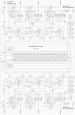
To me it does not look like the rails add when switched.
However, we could be looking at half of a balanced circuit.
An example;
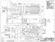
The Ling TP-850 has a balanced output and makes a measly 800W to 1 Ohm from a +/- 40V supply.
Attachments
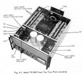
schematic.
(the whole manual is here: http://www.bunkerofdoom.com/lit/ling_TP850.pdf )
(the whole manual is here: http://www.bunkerofdoom.com/lit/ling_TP850.pdf )
Attachments
- Status
- This old topic is closed. If you want to reopen this topic, contact a moderator using the "Report Post" button.
- Home
- Amplifiers
- Solid State
- 20KW POWER AMP SCHEMATIC