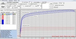
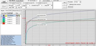
MJE15035 looks good but MJE15034 seems to be very different from my transistors, direct samples from ON Semi. Maybe you have a fake transistor?!
I did direct samples from Onsemi, however such hfe spread of mje devices seems depends on from country of origin. Chinese devices used to have such wide hfe spread, thus low quality production.
Last edited:
hFE is affected by Tj.........The Hfe would increase a bit in each test (is it affected by heat ?). ...........
As Tj increases hFE increases.
But, I would expect similar increase for both NPN and PNP.
Your results don't show that NPN to PNP correlation.
hFE is affected by Tj.
As Tj increases hFE increases.
But, I would expect similar increase for both NPN and PNP.
Your results don't show that NPN to PNP correlation.
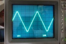
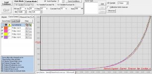
I did another test. Yes, the hFE increase is indeed similiar. BTW, I find Locky curve tracer is a very convenience and useful DIY tool.
Attachments
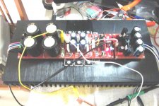
I finally fire up the board and the current readings are fairly close to Roender rating –
Q17 collector – 1.1 mA
Q13/11 collector – 9.2 mA
MJE15035/34 R15 – 80 mA
Shunt read 39V & main is 36V. For basis, it started at 29°C for 185 190 190 mA, and settled at 175 185 185 mA after heat sink heat up and stabilized at 45°C, power TRs are 47°C.
For the Shunt, MJE15034/35 run very hot at 53°C, is there a problem?
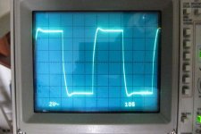
For dummy resistive 8R load test; the square wave looks very good without ringing (1 KHz to 100 KHz). Then, I parallel a 1 uF capacitor to the load, I have oscillation, tune up power and fuse brown.
What’s next ?
Q17 collector – 1.1 mA
Q13/11 collector – 9.2 mA
MJE15035/34 R15 – 80 mA
Shunt read 39V & main is 36V. For basis, it started at 29°C for 185 190 190 mA, and settled at 175 185 185 mA after heat sink heat up and stabilized at 45°C, power TRs are 47°C.
For the Shunt, MJE15034/35 run very hot at 53°C, is there a problem?
For dummy resistive 8R load test; the square wave looks very good without ringing (1 KHz to 100 KHz). Then, I parallel a 1 uF capacitor to the load, I have oscillation, tune up power and fuse brown.
What’s next ?
Attachments
I finally fire up the board and the current readings are fairly close to Roender rating –
Q17 collector – 1.1 mA
Q13/11 collector – 9.2 mA
MJE15035/34 R15 – 80 mA
Shunt read 39V & main is 36V. For basis, it started at 29°C for 185 190 190 mA, and settled at 175 185 185 mA after heat sink heat up and stabilized at 45°C, power TRs are 47°C.
For the Shunt, MJE15034/35 run very hot at 53°C, is there a problem?
For dummy resistive 8R load test; the square wave looks very good without ringing (1 KHz to 100 KHz). Then, I parallel a 1 uF capacitor to the load, I have oscillation, tune up power and fuse brown.
What’s next ?
You should insert in series with the output an 1...2uH air coil paralleled with some low ohm 2W resistor for supreme stability in any capacitive load.
For any real load this isn't necessarily unless you are using some very capacitive speakers.
Lee, the power dissipation of the shunt's MJE - transistors results from the output voltage of the shunt's transformer.
I myself am using a transformer with 34VAC secondaries, and my MJEs are not getting as hot as yours.
You have asked: what is next?
What about listening to the beautiful music that the FC-100 is producing?
Best regards - Rudi_Ratlos
I myself am using a transformer with 34VAC secondaries, and my MJEs are not getting as hot as yours.
You have asked: what is next?
What about listening to the beautiful music that the FC-100 is producing?
Best regards - Rudi_Ratlos
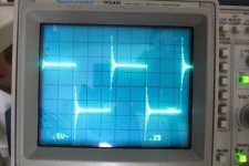
Hello, I did some testing for 8R resistor load at 20KHz. One channel is fine, another is overshoot, slower slew rate and non-linear. anyway to fine tune ? thanks for help. I haven't put in the output coil.
Attachments
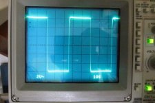
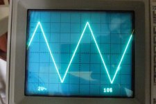
There is certainly a visual difference on the scope.
Is the "system" safe enough to connect a good speaker?
What does it sound like? Is that difference audible? Subtle or obvious?
Yesterday evening, I plug in my favorite Dynaudio contour 1.4 bookshelf speaker. The amp has good control over bass, smooth vocal and from time to time give me surprise. However, it is not forgiving on poor source.
As for the high, one channel is more airy, surprisingly it is belong the one with square wave overshoot

Thanks for that report Peter.
I had no idea whether your different channel would be audible.
You have confirmed it is audible.
That was quite a small overshoot, many are worse than this.
I explain that as over amplification of transients. This leads to an emphasis of HF that is not there in the real signal.
This may also relate to you hearing something added to poor sources.
I explain that as over amplification of transients. This leads to an emphasis of HF that is not there in the real signal.
This may also relate to you hearing something added to poor sources.
Yep, a little boost in HF does that.
Finished building both channels of FC-100. The led's from the front end of both channels are lit and DC out 3mv and 5mV.
Regarding bias i have some problems: on one channel i use 5 diodes and i can adjust voltage accordingly but on the other channel where two TT diodes are having a higher voltage i need to bypass them in irder to adjust bias confortably.
Is ok to work with 4 diodes (two shorted) or should i follow Rudi's solution with shottky diode ?
Unfortunately my test heatsinks are small and they become hot pretty fast.
I'm soooo curious to hear the music
Both channels sings nice
atupi, did you match the driver transistors?
I didn't matched. But I recently purchased some transistors and managed to get two good matched pairs for MJE15028/15030. I am wondering how much beneficial to replace them?
also, if I increase the value of C8,9 15pf, will it help to trim down the overshoot?
thanks
Attachments
- Status
- This old topic is closed. If you want to reopen this topic, contact a moderator using the "Report Post" button.
- Home
- Amplifiers
- Solid State
- Roender's FC-100 prototype and builder's thread