It is plausible considering the UBE temperature coefficient (ca. 2,2 mV/K) and the exponential Ic vs UBE law .Finally, I am really surprised how much difference a few C degrees in device temperature has made to the bias current imbalance. 185mA to 245mA thats 32% difference !!!
Last edited:
Jean: if you succeed with step 2 (my post #580): switch power off again, remove the bulb-tester, preset the potentiometer to 0 Ohm
and remove one of the "Bypass - TT-diode" jumpers.
(I see 2 diodes being bypassed on your picture).
You need a string of 5 active diodes for efficient thermal compensation.
Ideally the TT-diode with the highest Vf (did you measure before?) shall be bypassed.
Then: adjust again - and have a big Scotch!
Best regards - Rudi
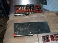
Hi, Rudi. Had a productive weekend. Adjusted both boards without problems finally! (See photos). Now, onto bigger heat sinks and appropriate enclosure. Oh yes, the sound is great and lots of oomphhhhh into 8 ohms. Thanks for all the help on this project. Another great build. Looking forward to the next...
Jean
Jean
Attachments
Jean: very nice to see that you replaced the "round" LEDs by square ones to maintain the thermal compound.
Does the ThermalTrak - diode chain consist of 5 active diodes?
It will be very, very hard (at least in my ears) to beat the sound of your FC-100!
So go on and give it adequate heatsinks and a nice case!
Thank you very much for the pictures that you published - I like them!
Best regards - enjoy the sound - Rudi
Last edited:
I reported a week or two back that round LEDs can be successfully reshaped to rectangular.
I just ran them across a file and finished with a diamond hone I keep for sharpening chisels.
I don't keep stock of rectangular LEDs and certainly would not let a few round LEDs stop me building a project that needed some flat faces. I don't buy bits in ones or twos. I buy when the out of stock list exceeds £50.
Last edited:
lucylu, It appears something is amiss as these supplies should only take a few VA from the mains. Concentrate on fundamentals initially.
Any signs of life such as LED's glowing?
Make sure you have the rectifier diodes in the right way round.
Same with the electro capacitors.
Reverse polarised capacitors can be a health hazard! They may start hissing, followed shortly after by exploding. Eye protection is recommended.
See if you can measure any DC Volts between each supply and 0 Volts. The 2.2 ohm resistors may be a convenient place to measure.
When you conclude there are no reverse polarity issues we can relax a bit. The 2.2 ohm resistors can behave as fuses, as I have discovered.
Please report your findings.
Keith
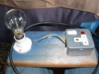
the shunt regulator draws a constant current from the PSU. About 50mA.
This is a significant load, bigger than some ClassAB power amplifiers when biased.
Check voltage and particularly polarities of voltages when the bulb is glowing.
Expect the voltage at the PSU to be <half the normal voltage.
When you are sure there are no catastrophic errors, use a higher wattage bulb to allow a higher transformer primary current to flow. This may just allow the PSU & regulator to reach >90% of normal voltage. If all is OK so far, then direct online powering comes next.
Remember that a shunt regulator dissipates all it's heat in the components. It gets hot.
45V @ 50mA for two polarities is 4.5W, that is a lot of heating.
Once you connect the front end the 21mA going into the amplifier you save 1.7W of heating. The heatsink should be noticeably cooler.
A little closer
Hi I changed both 2r2 resistors thanks Keith,the old ones read 48.5k and zero ??..so i have power as far as bd139 and 140 but no further, leds are on,,,on switch on my bulb flashes ?,,on switch off one led is very slow to go out. Any ideas ? before i start checking other parts john
Hi I changed both 2r2 resistors thanks Keith,the old ones read 48.5k and zero ??..so i have power as far as bd139 and 140 but no further, leds are on,,,on switch on my bulb flashes ?,,on switch off one led is very slow to go out. Any ideas ? before i start checking other parts john
John, Firstly the heatsinks. Presumably you have powder coated ones with the holes pre-drilled, so there should be no problems with burrs or metal particles piercing the insulating washers on the MJE devices to short the collectors. Also, you have presumably used insulating bushes on the MJE sides of the bolts?.
In the following I am using Roender's part numbers from the earliest posts on the design. Not certain what Rudi is using in his documentation. The BD139/140 devices are current generators. The LED's are voltage references like Zener diodes. The combination of the LED's and the value of R3/4 define the value of the constant current that is being sourced from the collectors of T1/T2. I measured 1.23V across R3 and R4. I = E/R 1.23/33R = 37mA
On the positive supply Q3,Q2 and Q6 are all emitter followers using NPN devices. Check all the devices in case you are using PNP where you should have NPN and vice versa. If these emitter followers are being correctly biased you should read Vbe's of about 0.7V on all three.
The voltage across R11 should be Q6 Vbe
The voltage between the "hot" ends of R9 and R11 should be Q2 Vbe
The voltage between the "hot" ends of R7 and R9 is Q3 Vbe.
What voltage are you reading across the Zeners?
Are they installed the right way around?
What voltage are you seeing on the BD 139/140 collectors? If zero, you may have a short to the heatsink.
Try and come up with a "game plan" when problem solving and avoid randomly removing parts as it takes a toll on the printed board and is rarely effective. You need to understand in your mind how the circuit works and use measurements/observations to get a handle on why it is not behaving as intended. There is definitey an element of problem solving as a "learned skill" thus people like me who were payed to fix electronic problems tend not to give up easily!
By the way, the failed 2.2R resistors are likely to continue failing untill you remove the fault(s) that are causing them to fail.
Bye
Keith
Last edited:
I have both shunts working.
At last it was driving me mad,,I had changed both bd140/139 from a stock i had,,,, but not until i received new ones from RS did it work,, suspect fake bd s but i cannot be sure or maybe not using a bulb tester....i have made lots of projects never had this type of problem before perhaps is was just my turn .") Thanks for advise Keith.....regards john
Thanks for advise Keith.....regards john
At last it was driving me mad,,I had changed both bd140/139 from a stock i had,,,, but not until i received new ones from RS did it work,, suspect fake bd s but i cannot be sure or maybe not using a bulb tester....i have made lots of projects never had this type of problem before perhaps is was just my turn .
Thanks for advise Keith.....regards johnHeat Sinks
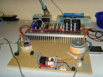
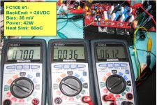
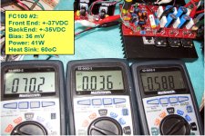
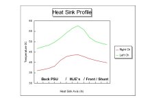
Further to my post #587, I moved to bigger heatsinks (25x150x350mm) and get different temperature profiles for each channel (see pic). One channel is running much hotter (or much cooler!) even though back end VDC is +-35, front end shunt is +-37 VDC, both biased @ 36mA and DC offset only +-0 to 3mV. The heat is from the MJE's. Is this difference normal for Thermatraks or is there a problem somewhere on one board ??? Amp sounds fine. Appreciate any input.
Jean
Attachments
Is this difference normal for Thermatraks or is there a problem somewhere on one board ??? Amp sounds fine. Appreciate any input.
Jean
Please measure the voltage dropped over R5 and also measure the R5 for both channels ( http://www.diyaudio.com/forums/soli...-stage-audio-power-amplifier.html#post1349109 )
Hi, Roender. Here are the values for R5:
Left Ch: 15.9 Ohms @ 1.09 V (Back PSU=34.3V, Shunt=37.4V)
Right Ch: 15.9 Ohms & 1.17 V (Back PSU=34.5V, Shunt=37.6V)
In the thermal profile, the heat comes of course from the NJL's not the MJE's as I mistakenly said...
As I mentioned in earlier posts, I did have some trouble in finally adjusting the right ch., I had one bad 2SA1360 which I replaced. Perhaps, some fault in others although they tested okay???
- Status
- This old topic is closed. If you want to reopen this topic, contact a moderator using the "Report Post" button.
- Home
- Amplifiers
- Solid State
- Roender's FC-100 prototype and builder's thread