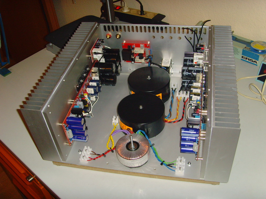
This is the result of last night's hard work:
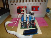
I have mounted the 3 needed transformers on the bottom ALU-plate.
May I give you (builders of the FC-100) two recommendations?
1) Twist the primary and secondary transformer windings as I did
2) Put some material to absorb vibrations (I used rubber slices) underneath the transformers
Luke: I counted 21 LEDs used in my FC-100 build so far.")
To use an ACRYL glass as top plate would be a nice option then.
I will now go on an and fix the heatsinks (channels) to the bottom plate.
Best regards - Rudi_Ratlos
An externally hosted image should be here but it was not working when we last tested it.
I have mounted the 3 needed transformers on the bottom ALU-plate.
May I give you (builders of the FC-100) two recommendations?
1) Twist the primary and secondary transformer windings as I did
2) Put some material to absorb vibrations (I used rubber slices) underneath the transformers
Luke: I counted 21 LEDs used in my FC-100 build so far.
To use an ACRYL glass as top plate would be a nice option then.
I will now go on an and fix the heatsinks (channels) to the bottom plate.
Best regards - Rudi_Ratlos

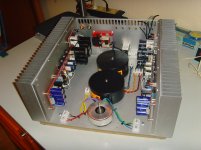
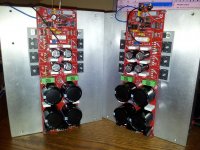
A good DIY-friend of mine, Klaus, who helped me a lot with the build of my ALU-case, sent me a picture of his FC-100 today.
During his build and quiescent current adjustment, he encountered no problems at all and is enjoying listening to the music.
The heatsink, as shown on the picture, is an intermediate solution.
Klaus will go and build two mono-blocks.
Best regards - Rudi_Ratlos
During his build and quiescent current adjustment, he encountered no problems at all and is enjoying listening to the music.
The heatsink, as shown on the picture, is an intermediate solution.
Klaus will go and build two mono-blocks.
Best regards - Rudi_Ratlos
Attachments
John,
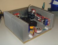
I had my heatsinks at hand, when I started the project.
The heatsinks of Klaus are an intermediate solution.
Please keep in mind that the PCBs are about 250mm long.
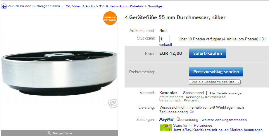
A "ready-to-go" case, the one that ZDR used for example (see attached image), will do it.
Best regards - Rudi_Ratlos
I had my heatsinks at hand, when I started the project.
The heatsinks of Klaus are an intermediate solution.
Please keep in mind that the PCBs are about 250mm long.
A "ready-to-go" case, the one that ZDR used for example (see attached image), will do it.
Best regards - Rudi_Ratlos
Attachments
I have not yet seen any FC-100 build applying a PI / EMV - filter (10 Ohm / 1µH) to the speaker's output.
Mihai said that the amp is stable without it, i second that but i'm gonna use it in my final amp.
What about Thiel like this in post #10?
http://www.diyaudio.com/forums/solid-state/94029-when-output-inductor-needed.html
zsaudio
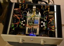
I am currently going on and integrate a source selection / volume attenuation into my FC-100 case.
The selector/attenuator is based on BurrBrowns (TI) PGA2311 - chip, which is controlled by a PIC 16F4550 µProcessor.
I prefer this solution to an ALPS-DualPotentiometer, to the Lightspeed-Attenuator, ..., and:
everything is controlled remotely by means of Infrared.
The digital PCBs will be placed on an ALU - U-bracket, which I will mount on the 3 tranformers - building "the second floor".
But this all takes a lot of time ...
Best regards - Rudi_Ratlos
P.S. The source selector / attenuator is DIYed - of course!
Attachments
Last edited:
- Status
- This old topic is closed. If you want to reopen this topic, contact a moderator using the "Report Post" button.
- Home
- Amplifiers
- Solid State
- Roender's FC-100 prototype and builder's thread