 .
.
It will take some time (and money), until I will be able to exhibit this AMP in my showcase beside the AMPs of Upupa Epos .Code:[QUOTE][/QUOTE]
Hats off to Upupa Epops's PCB 's. These are state of the art; hope to reach that level.
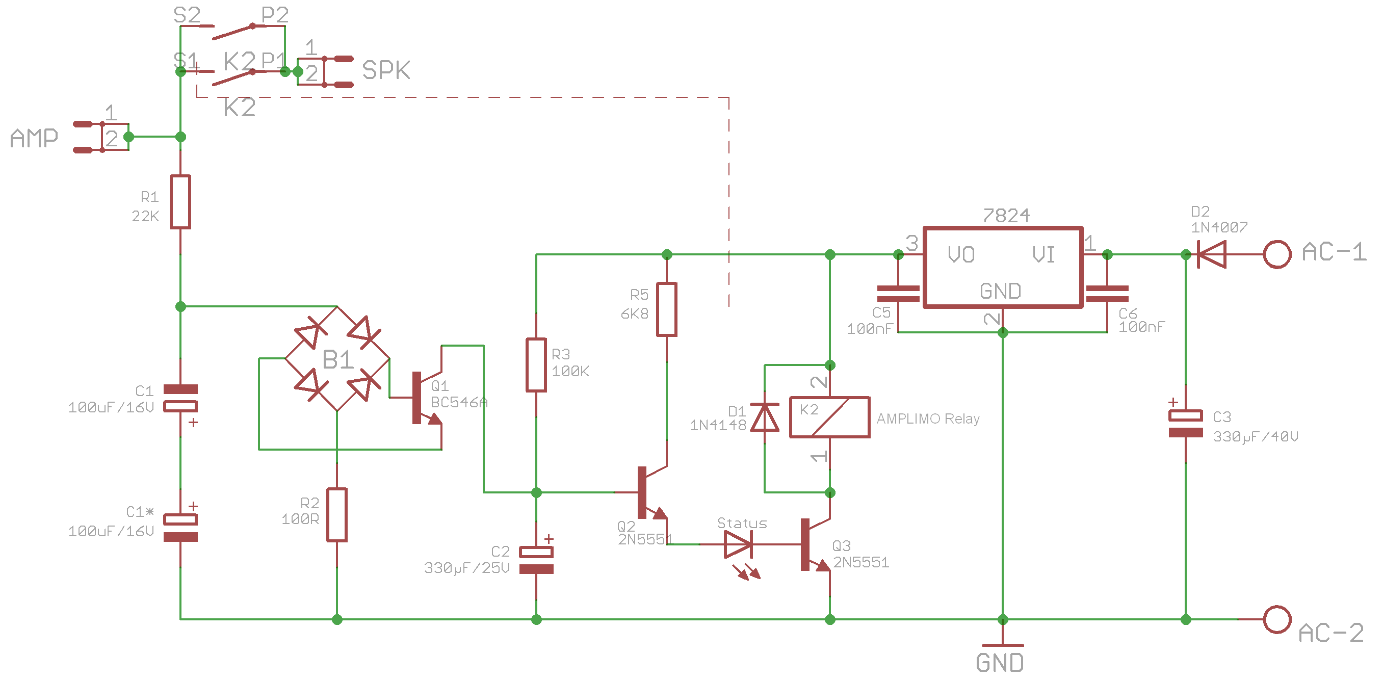
I finally fixed the "AMPLIMO-relay" issue.
Of course my problems had nothing to do with the relay itself.
The reason for them was that my EAGLE's components' library contains 2 versions of the 2N5551 transistor:
a TO92-CBE version (which is discontinued) and a TO92-EBC version (which is the current one).
I picked up the wrong CBE version inadvertently and used it in my layout.
@ZSOLT: you have to rotate the 2N5551 transistors on your PCB!
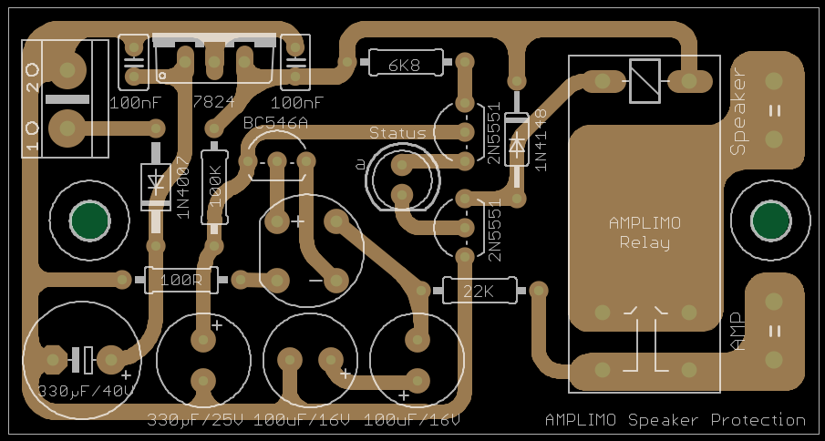
This is the resulting schematics:
and layout:
I will now go on and finish the construction of the test-rig for my FC-100.
An externally hosted image should be here but it was not working when we last tested it.
Best regards - Rudi_Ratlos
P.S. Thank you, Andrew, very much for your advise concerning the position of the LED.
The speaker-protection circuit nows works flawlessly.
I've 5 of those Amplimo Relais
Gentlemen,
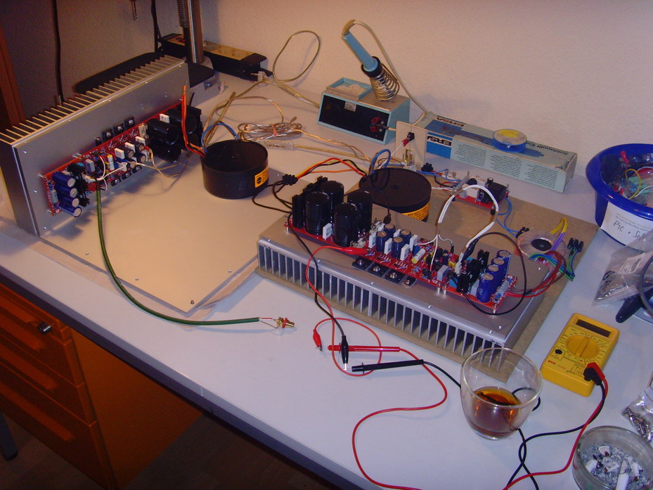
I had some time this morning and did the first PowerOn.
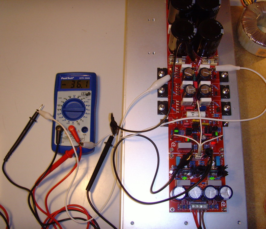
No problems at all.
I could easily adjust the quiescent current / bias so that 36mV drops across 2 0R10 emitter resistors - and:
I am using 5 internal ThermalTrak diodes.
I will now leave this setup as is for some while, then switch it off, remove the bulb tester (!) and adjust again.
This is what I wanted to prove / show you with my latest posts: the "series - PCBs" are absolutely flawless,
and if you do your build with some care and measure the components (resistors, transistors, ...), before you solder them,
this AMP will work "from the scratch".
Best regards - Rudi_Ratlos
I had some time this morning and did the first PowerOn.
No problems at all.
I could easily adjust the quiescent current / bias so that 36mV drops across 2 0R10 emitter resistors - and:
I am using 5 internal ThermalTrak diodes.
I will now leave this setup as is for some while, then switch it off, remove the bulb tester (!) and adjust again.
This is what I wanted to prove / show you with my latest posts: the "series - PCBs" are absolutely flawless,
and if you do your build with some care and measure the components (resistors, transistors, ...), before you solder them,
this AMP will work "from the scratch".
Best regards - Rudi_Ratlos
Last edited:
One wonders why so many posts appeared contradicting the designer's instructions to use 5 diodes for correct tempco.I could easily adjust the quiescent current / bias so that 36mV drops across 2 0R10 emitter resistors - and:
I am using 5 internal ThermalTrak diodes........
This is quite a typical summer day in Northern Germany today: rainy, storm, 16 degrees.
No way to go out for a walk, and I continued the build of the 2nd channel of my FC-100.
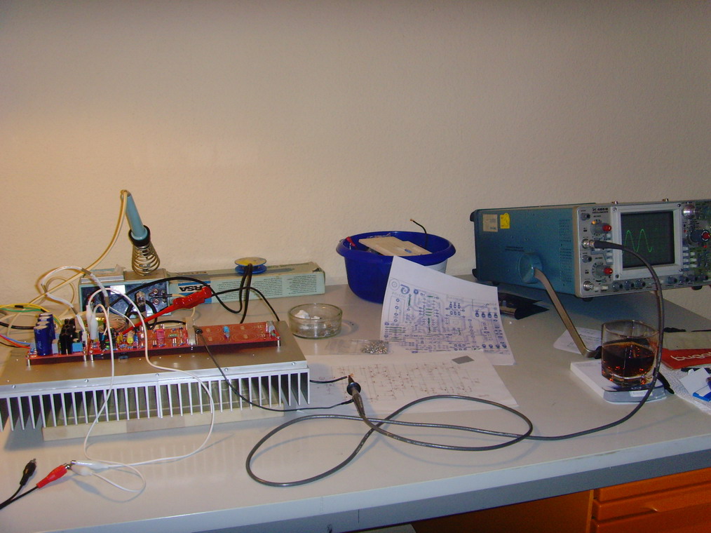
I tested the frontend and applied a 500Hz sine wave to the input:
The result looks like "works as designed".
If it continues to rain, I will proceed with the backend and the backend-PSU this afternoon.
Best regards - Rudi_Ratlos
No way to go out for a walk, and I continued the build of the 2nd channel of my FC-100.
I tested the frontend and applied a 500Hz sine wave to the input:
The result looks like "works as designed".
If it continues to rain, I will proceed with the backend and the backend-PSU this afternoon.
Best regards - Rudi_Ratlos
I completed the 2nd (right) channel of my FC-100 this afternoon, cleaned if with Isopropanol, checked it with a magnifying glass
and then switched power on.
I didn't once more have any problems adjusting the quiescent current / bias, so that 36mV drops across two opposite emitter resistors,
and I am once more using 5 internal TT - diodes.
I am convinced now that I have had some bad luck, when I built the prototype.
The NJL - transistors (the integrated TT-diodes) that I used, when I built the prototype, did not adhere
to the specifications published in the datasheet.
The NJL - transistors that I am using currently, come from the current OnSemi batch and behave correctly.
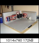
I will now proceed with my ALU-case.
Maybe that this is not interesting for you, and I will not post many more pictures.
@ those of you, who ordered the NJL-transistors from me:
The transistors are on their way to me, I will have them tomorrow or on Friday, I will then match them and send them to you as soon as possible.
Best regards - Rudi_Ratlos
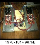
P.S.: If you do it like me and build a stereo amplifier in one case (in contrast to 2 mono-blocks):
Be careful where to tap your heatsinks! Keep in mind to "mirror" the drill holes!
and then switched power on.
I didn't once more have any problems adjusting the quiescent current / bias, so that 36mV drops across two opposite emitter resistors,
and I am once more using 5 internal TT - diodes.
I am convinced now that I have had some bad luck, when I built the prototype.
The NJL - transistors (the integrated TT-diodes) that I used, when I built the prototype, did not adhere
to the specifications published in the datasheet.
The NJL - transistors that I am using currently, come from the current OnSemi batch and behave correctly.
I will now proceed with my ALU-case.
Maybe that this is not interesting for you, and I will not post many more pictures.
@ those of you, who ordered the NJL-transistors from me:
The transistors are on their way to me, I will have them tomorrow or on Friday, I will then match them and send them to you as soon as possible.
Best regards - Rudi_Ratlos
P.S.: If you do it like me and build a stereo amplifier in one case (in contrast to 2 mono-blocks):
Be careful where to tap your heatsinks! Keep in mind to "mirror" the drill holes!
Last edited:
I have been busy in the past days matching about 75 pairs of NJL0281DG / NJL0302DG transistors for the ones, who ordered.
This afternoon I have had some time to go on with my FC-100 build.
I adjusted the quiescent current / BIAS once more (without the bulb tester this time): 36.3 mV voltage drop across 2 emitter resistors
and measured the DC offset: 0.8mV (!!).
I then attached a "simulated speaker" to the AMP's output:

This looks very well!
I will connect a pair of real speakers tomorrow and will tell you about my first sound-impressions.
Best regards - Rudi_Ratlos
This afternoon I have had some time to go on with my FC-100 build.
I adjusted the quiescent current / BIAS once more (without the bulb tester this time): 36.3 mV voltage drop across 2 emitter resistors
and measured the DC offset: 0.8mV (!!).
I then attached a "simulated speaker" to the AMP's output:
This looks very well!
I will connect a pair of real speakers tomorrow and will tell you about my first sound-impressions.
Best regards - Rudi_Ratlos
Last weekend I was happy to find enough time build my amp.
All parts were on stock. On Monday evening I was able to
plug the Amp to my loudspeaker in der living room.
I was very curious about the sound. The first impression was OK so far,
but not as well as my favorite Amp, the Symasym TO264.
I missed precision. Then I made a break of 1h. I was wondered, if I
continused my session: The sound was better than before! - Yeahh!
Now, after only a few hours sound is very, very good. I am impressed!
The heatsink is 140x400x40. After 1h it is about 50°C.
@all
I recommend to build this wonderful amp asap.
claus1968

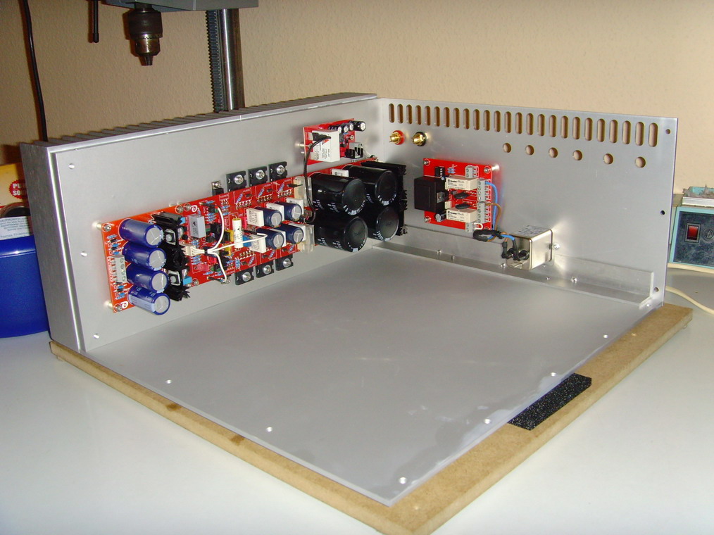
After several weeks of holiday I have gone on with the build of my FC-100 (to be more precise: with the build of the case for my FC-100) today.
http://www.abload.de/img/bp007emqxk.jpg
I have finally finished the back panel and mounted the "Soft-Power-On - PCB" onto it.
It makes fun to see my FC-100 grow up, very slowly, since everything is DIYed, and I wonder, how it will look like, when it is finally finished.
I have many choices concerning the top- and front-plate: ALU, wood, ACYRL, stone (schist??), ...
Next step will be to mount the needed transformers and stands to the bottom plate.
I will keep on showing my progress in this thread.
Isn't there anyone else to show his progress of his FC-100 buid?
Best regards - Rudi_Ratlos
If you cannot open the URL of my "picture-provider": I apologize.
Here it is once more:
Best regards - Rudi
Here it is once more:
An externally hosted image should be here but it was not working when we last tested it.
Best regards - Rudi
- Status
- This old topic is closed. If you want to reopen this topic, contact a moderator using the "Report Post" button.
- Home
- Amplifiers
- Solid State
- Roender's FC-100 prototype and builder's thread