Matching the NJL transistors
... is not an easy job.
I have etched some small PCBs representing this schematics:
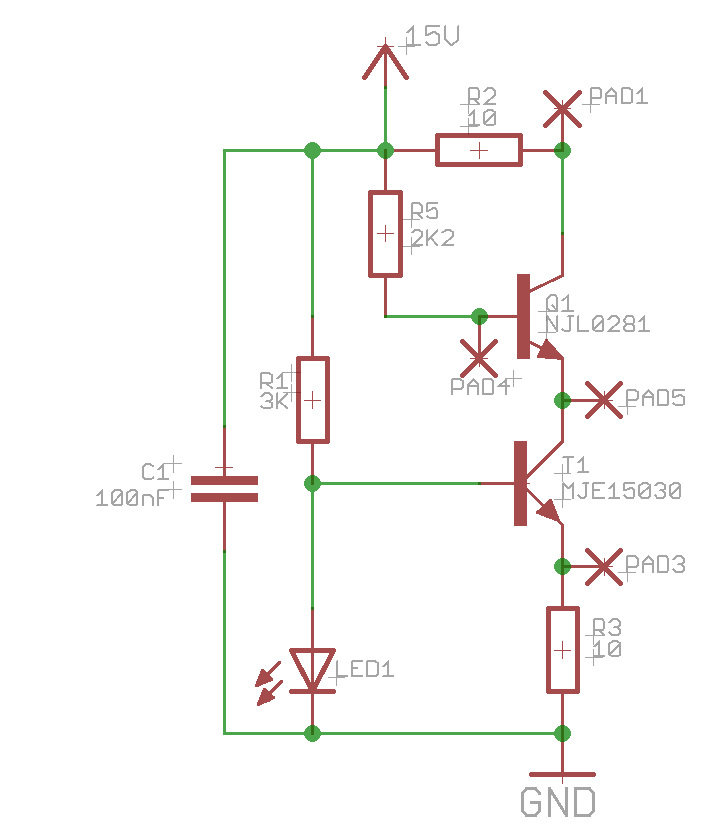
and measured a NJL0281DG.
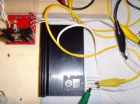
As power supply I use a LAPTOP PSU rated at 15V/4A.
The results: the current that is flowing into the collector of the NJL is 160mA, the current flowing into its base is 2.49mA.
The resulting Hfe is 64.2, which is smaller than the documented minimum of 75 in the OnSemi datasheet.
The reason for this difference is that OnSemi does its measurements with a collector current of at least 500mA
and having a different VCE (5V), while my VCE is about 6V.
I cannot increase the collector current very much without risking the thermal death of transistor T1.
Nevertheless I think that this little PCB will help finding "matched" triples of NJL transistors.
Best regards - Rudi_Ratlos
... is not an easy job.
I have etched some small PCBs representing this schematics:
and measured a NJL0281DG.
As power supply I use a LAPTOP PSU rated at 15V/4A.
The results: the current that is flowing into the collector of the NJL is 160mA, the current flowing into its base is 2.49mA.
The resulting Hfe is 64.2, which is smaller than the documented minimum of 75 in the OnSemi datasheet.
The reason for this difference is that OnSemi does its measurements with a collector current of at least 500mA
and having a different VCE (5V), while my VCE is about 6V.
I cannot increase the collector current very much without risking the thermal death of transistor T1.
Nevertheless I think that this little PCB will help finding "matched" triples of NJL transistors.
Best regards - Rudi_Ratlos
Attachments
voltage across T1 should not be a problem.
Try to set up your supply voltage such that T1 is dropping about 1.5V.
This will give a dissipation of 6W @ 4A. A decent heatsink will save this transistor.
If you adjust the base stopper of T2 to get your Vce to 5V then you can check both the base current and the Vbe at near your test values of 5Vce and 4A without risking any components.
If you want you can repeat these measurements at 2A and 1A.
I will try, Andrew.
I suppose that OnSemi measures the transistors at a lower supply-voltage: 10-12VDC.
I am lucky to have my LAPTOP power supply and will be able to adjust the supply voltage by means of a 7805.
Maybe I will be able to adjust to IC=500mA @ VCE = 5VDC.
Best regards - Rudi_Ratlos
I suppose that OnSemi measures the transistors at a lower supply-voltage: 10-12VDC.
I am lucky to have my LAPTOP power supply and will be able to adjust the supply voltage by means of a 7805.
Maybe I will be able to adjust to IC=500mA @ VCE = 5VDC.
Best regards - Rudi_Ratlos
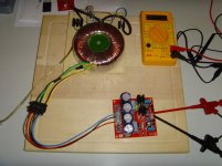
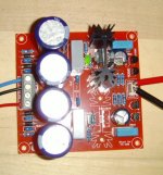
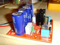
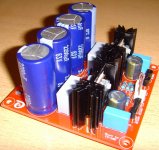
Since we have a public holiday in Germany today, I had some time and soldered the first PCB, a shunt-regulator board.
I am missing a heatsink for the negative rail as you can see.
(I will unsolder my prototype tonight - LoL.)
I connected a 1.8K resistor to the output giving a load of approx. 21 mA.
The transformer used has 2 x 35 VAC secondaries; this time I am using a 36V Zener diode.
The shunt works flawlessly.
Did I ever thank Mihai for developping this wonderful AMP?
If not - thank you, Mihai
Best regards - Rudi_Ratlos
Attachments
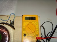
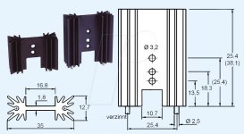
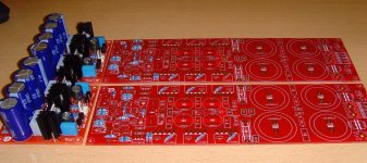
I have been asked if I am sure that the solder pins of the heatsinks that I am using (see attached image) are "electrically coupled"?
I am not sure, but when I measure the resistance between the 2 solder pins, my multimeter returns a value of 0 Ohm.
The datasheet does not reveal, if a connection between a solder pin and the body of the heatsink exists.
Does anybody know for sure?
Best regards - Rudi_Ratlos
I am not sure, but when I measure the resistance between the 2 solder pins, my multimeter returns a value of 0 Ohm.
The datasheet does not reveal, if a connection between a solder pin and the body of the heatsink exists.
Does anybody know for sure?
Best regards - Rudi_Ratlos
Attachments

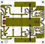
Koldby, I intented to connect the GND planes on top and on the bottom to the GND plane in the middle of the PCB by means
of the soldering pins of / and the heatsink.
Since I am no more convinced about the conductivity, I will advise the builders to solder a wire across the black lines.
Best regards - Rudi_Ratlos
of the soldering pins of / and the heatsink.
Since I am no more convinced about the conductivity, I will advise the builders to solder a wire across the black lines.
Best regards - Rudi_Ratlos
Attachments
Since I am no more convinced about the conductivity, I will advise the builders to solder a wire across the black lines.
Best regards - Rudi_Ratlos
That is good advise in my book

Koldby
Gentlemen, I love pictures!
Please do me the favour and post pictures of the current status of your FC-100 build in this thread.
Find enclosed a picture of my 1.st shunt PCB.
It works as designed and - yes: I have connected the heatsinks to the GND-plane in the middle of the PCB via a solid wire on its solder side.
I will start with the 1st AMP PCB today.
Best regards - Rudi_Ratlos
Attachments
Last edited:
Re: FC-100
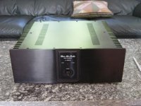
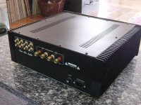
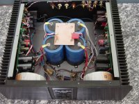
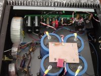
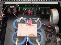
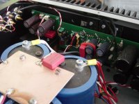
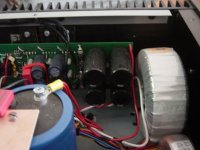
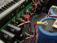
Here is my FC-100 build.
It is the original PCB´s and in a chassis bought in Hong Kong, therefore the brand name on the faceplate and backplate.
This is actually for sale as I have to reduce the number of amps in my household!
Shoot me a PM if you would like to know more.
Best
Koldby
Here is my FC-100 build.
It is the original PCB´s and in a chassis bought in Hong Kong, therefore the brand name on the faceplate and backplate.
This is actually for sale as I have to reduce the number of amps in my household!
Shoot me a PM if you would like to know more.
Best
Koldby
Attachments
Gentlemen,
my build of the FC-100 is "on hold":

http://www.abload.de/img/fc-100oefds.jpg
since I am struck with a whole bunch (50 pcs.) of "fake 2SA1360" transistors right now:

http://www.abload.de/img/2sa13608jczf.jpg
These are not genuine Toshiba transistors - I am absolutely sure about it, but Toshiba Germany has this to be confirmed by Toshiba Japan!
And this will take a long time.
Please be sure to buy your transistors from reliable distributors only!
In the meantime I will proceed with the heatsinks for the FC-100:

http://www.abload.de/img/hs0010qfzb.jpg

http://www.abload.de/img/front-20120507_1122100qdiu.jpg
Best regards - Rudi_Ratlos
Last edited:
Nice Rudi....very nice
You are on the mood....i hope it sounds the way you like.... Roender is a great designer...for sure it will sound awesome.
Well... Roender is a real designer....has a degree of Physics i think and have studied deeply amplifiers.
I would like to see your pictures full size (and full resolution too) .... sadly i could read you prefer to do this way...it is all right this way too...i use to copy and expand here in my screen.
regards,
Carlos
- Status
- This old topic is closed. If you want to reopen this topic, contact a moderator using the "Report Post" button.
- Home
- Amplifiers
- Solid State
- Roender's FC-100 prototype and builder's thread