Took me a while to see that one pic is upside down relative to the other.
It also seems the red rectangle is irrelevant to the thermal coupling.
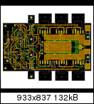
I can see two To92 directly coupled together.
I can also see two To92 sandwiching a rectangular LED as a thermally coupled triplet. These are above the red capacitor, which in the upside down pic look as though they are located below the red cap.
It also seems the red rectangle is irrelevant to the thermal coupling.
I can see two To92 directly coupled together.
I can also see two To92 sandwiching a rectangular LED as a thermally coupled triplet. These are above the red capacitor, which in the upside down pic look as though they are located below the red cap.
My first Group Buy
Hello Rudi and Metal.
I have just added my name to the Group Buy spreadsheet in the hope that it is still open. This is my first involvement in a group buy and I'm not sure what happens next.
What I would like to know is have you worked out any final costs yet and what are the shipping costs likely to be to the UK?
Seasons greetings to all")
Roy.
Hello Rudi and Metal.
I have just added my name to the Group Buy spreadsheet in the hope that it is still open. This is my first involvement in a group buy and I'm not sure what happens next.
What I would like to know is have you worked out any final costs yet and what are the shipping costs likely to be to the UK?
Seasons greetings to all
Roy.
Roy,
METAL and I are currently very busy reading through Dr. Self's "Amplifier Design Handbook, Chapter 18: Grounding, cooling and layout"
to offer you the best possible layout (in our humble opinions).
Once we both have settled about the final design and layout (only then will I know, how big the PCBs will be), we will give you the price of the PCBs
and I will tell you, what the "small kit", which I will be goiing to offer, will include besides of the PCBs.
For example: the FUTABA MPC74 Emitter Resistors, the NJL - output transistors, hard to get caps, ...
The price for shipping is 3.45€ worldwide, as long as the parts fit into a coated letter and do not weigh more than 500 gramm.
The payment will be done via PAYPAL.
Best regards - Rudi_Ratlos
Please, Pooge: I kindly ask you to keep off this thread!
If you want to do a new design, to offer your own group-buy: go ahead and open a new thread, but please do not use my thread for your purposes!
METAL and I have been reading and investigating a lot about proper layout, grounding, ...
We read "Designing Audio Power Amplifiers" by Bob Cordell, Chapter 16: "Power Supplies and Grounding", "Audio Power Amplifier Design Handbook" by Douglas Self, Chapter 18: "grounding, Cooling and Layout", articles of Randall Aiken about Star Grounding, ...,
to offer a proven and respectable layout.
This took some time, as I wrote before.
METAL and I are nearly done, and we think that we will show to the ones, who are interested in this (!) group-buy, the final result either tomorrow or on Sunday.
I do not count you, Pooge, to the "interested party list", and I ask you very friendly to not post in this thread any more.
Best regards - Rudi_Ratlos
Last edited:
 Posts by Pooge regarding his plans for a competing GB have been deleted by moderation.
zdr is right. I modified the orientation of T2.
I don't know how, but I think we have both mirrored J1/J2 (T1/T2 in Eagle) footprints. Look at this post which seems to show correct configuration:
http://www.diyaudio.com/forums/soli...tage-audio-power-amplifier-6.html#post1349504
It must be coming from some early brd file that was posted. Please doublecheck it with 2SK170 datasheet.
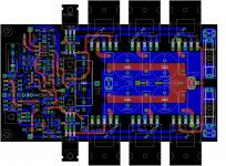
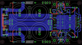
Current progress
Here is a quick peek to how the AMP PCB WILL basically look like. I believe this will be the final version for this AMP PCB. I asked Rudi to take care of the 2SK170 while I am working on the PSU PCB, basically thanks to zdr who pointed out this 2SK170 issue!
I am still working on the SPU part, the attached snapshot should also give an idea of how the PSU PCB shall look like. Actually, aligning components correctly took longer than I expected for this PCB.
After reading thru Self's and Cordel's books, I believe this is the correct way of doing GND:
- Signal (Both books discussed it).
- Speaker/Zobel GND (described in Dr. Self, chapter 18).
- RG (described in Dr. Self, chapter 18) used to connect decoupling caps on AMP PCB to PSU, this GND connection should be in the RG area, rather than the Speaker/Zobel or signal GND.
If you examine both PCBs, you will notice this has been applied.
regards
metal
Attachments
Rudi and Metal,
Nice job till now ... keep up!
Q: Your plan is to use only one power supply for both channels? I do not recommend that.
What's the point in making large power supply lines, grater than speaker lines? Both should have the same current capabilities
Happy New Year!
Mihai
Nice job till now ... keep up!
Q: Your plan is to use only one power supply for both channels? I do not recommend that.
What's the point in making large power supply lines, grater than speaker lines? Both should have the same current capabilities
Happy New Year!
Mihai
I need this PSU to be versatile, this is why you see more than one spade and pad where you expect only one, it will not only be dedicated for this amplifier. So thick lines were used, also larger caps supported.
Having a shunt-reg is a plus on the same PSU PCB, really nice.
Having a shunt-reg is a plus on the same PSU PCB, really nice.
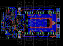
Good news
Finally, the amplifier PCB is finished, no more changes will be carried out (I hope!)
Still there are few things I have to finish on the PSU PCB after Rudi and I talk about them, and then we are done!
I hope that these PCBs find their way into DIYers hearts
Finally, the amplifier PCB is finished, no more changes will be carried out (I hope!)
Still there are few things I have to finish on the PSU PCB after Rudi and I talk about them, and then we are done!
I hope that these PCBs find their way into DIYers hearts
Attachments
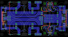
Gentlemen,
METAL and I finished the layout of both the AMP- and the PSU - PCB and we are currently inspecting the GERBER files
that result from the EAGLE - .brd files.
http://www.abload.de/img/fc-amp-gerbvmhlpr.png
I checked the underlying schematics twice, compared it with ZDR's schematics and with Mihai's Spice - file:
I am very sure that the wiring is correct.
How shall we go on now?
Mihai suggested to prototype the PCBs before offering them to the community.
The minimum number of PCBs that I can order in the aimed quality is 10.
The price for an AMP PCB (size: 136 x 74mm) is 14.50€ then; the price for a PSU PCB (size: 162 x 87mm) is 15.50€.
Do you think that prototyping is necessary?
If so: will there be 4 of you (besides me) who are willing to evaluate METAL's and my version of Mihai's amplifier and buy 2 pcs of each PCB?
What colour should the PCBs have? Red, green or blue soldermask colour with white silkscreen or do you want something special for this AMP?
Black and white or white and Black?
Best regards - Rudi_Ratlos
METAL and I finished the layout of both the AMP- and the PSU - PCB and we are currently inspecting the GERBER files
that result from the EAGLE - .brd files.

http://www.abload.de/img/fc-amp-gerbvmhlpr.png
I checked the underlying schematics twice, compared it with ZDR's schematics and with Mihai's Spice - file:
I am very sure that the wiring is correct.
How shall we go on now?
Mihai suggested to prototype the PCBs before offering them to the community.
The minimum number of PCBs that I can order in the aimed quality is 10.
The price for an AMP PCB (size: 136 x 74mm) is 14.50€ then; the price for a PSU PCB (size: 162 x 87mm) is 15.50€.
Do you think that prototyping is necessary?
If so: will there be 4 of you (besides me) who are willing to evaluate METAL's and my version of Mihai's amplifier and buy 2 pcs of each PCB?
What colour should the PCBs have? Red, green or blue soldermask colour with white silkscreen or do you want something special for this AMP?
Black and white or white and Black?
Best regards - Rudi_Ratlos
- Status
- This old topic is closed. If you want to reopen this topic, contact a moderator using the "Report Post" button.
- Home
- Amplifiers
- Solid State
- Roender's FC-100 prototype and builder's thread