Hi Sheldon,
There is a better design, but we will not discuss it in this thread. Rudi has already stated that we will not enforce serious changes at this stage. Forgive my loud thinking.
No need for forgiveness. A higher spec'd regulator would not be a problem. I just question whether there would be any real benefit for this front end. Sometimes "better" is the enemy of "good", if it slows completion of the project.
One area that will make a difference in noise floor, is to make sure all the common and earth schemes are done well on the boards (seems like they are), and for the builder to experiment with transformer placement and orientation - and transformer type, if you have the choice (check Mihai's recommendations). These will make an audible difference.
Sheldon
Gentlemen,
the longer I think about it, the more I feel content with the decision that METAL and I have taken:
1) not to add any PSU ingredient on Mihai's RMI FC-100 AMP PCB at all
2) but offer you the best PSU you can think about as a separate PCB
This is what I am talking about:
http://www.abload.de/img/topviewfgzpu.png
A PSU PCB, containing the backend PSU on the left side, with 2 full-bridge rectifiers, with heatsinks provided, C - R/L - C filter,
supporting caps of 35mm diameter, LED indicators, bleeder-resistors, ..., and - on the right side of the PCB: Mihai's shunt-regulator.
This PSU-PCB is dedicated to Mihai's AMP. It is very flexible: you can use one PSU-PCB and one / one transformer to provide power
to both the backend- and frontend-sections of each channel or you can build a dual-mono design with two / two transformers
for the backend / frontend power or ...
And: you do not have to worry about STARGROUND any more.
STARGROUND will be in any case the 4 pin connector block (run 1 or 2 wires to the AMP-PCBs GND plane, 1 or 2 wires to the Speaker-Return)
in the middle of the PSU-PCB.
The implementation of this PSU-PCB for Mihai's AMP will still take several hours.
METAL and I want to offer you the best PSU available for this AMP.
Is there anything that I have overseen? Please tell me.
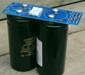
This will be my cooling fundament (400 x 170 mm) for Mihai's AMP.
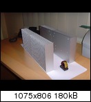
http://www.abload.de/img/joe002nlbrm.jpg
I think that it will do its job.
Best regards - Rudi_Ratlos
the longer I think about it, the more I feel content with the decision that METAL and I have taken:
1) not to add any PSU ingredient on Mihai's RMI FC-100 AMP PCB at all
2) but offer you the best PSU you can think about as a separate PCB
This is what I am talking about:

http://www.abload.de/img/topviewfgzpu.png
A PSU PCB, containing the backend PSU on the left side, with 2 full-bridge rectifiers, with heatsinks provided, C - R/L - C filter,
supporting caps of 35mm diameter, LED indicators, bleeder-resistors, ..., and - on the right side of the PCB: Mihai's shunt-regulator.
This PSU-PCB is dedicated to Mihai's AMP. It is very flexible: you can use one PSU-PCB and one / one transformer to provide power
to both the backend- and frontend-sections of each channel or you can build a dual-mono design with two / two transformers
for the backend / frontend power or ...
And: you do not have to worry about STARGROUND any more.
STARGROUND will be in any case the 4 pin connector block (run 1 or 2 wires to the AMP-PCBs GND plane, 1 or 2 wires to the Speaker-Return)
in the middle of the PSU-PCB.
The implementation of this PSU-PCB for Mihai's AMP will still take several hours.
METAL and I want to offer you the best PSU available for this AMP.
Is there anything that I have overseen? Please tell me.
This will be my cooling fundament (400 x 170 mm) for Mihai's AMP.

http://www.abload.de/img/joe002nlbrm.jpg
I think that it will do its job.
Best regards - Rudi_Ratlos
Last edited:
My suggestion is mostly a practical one. The front end and back end of the amp are on opposite sides of the board, so why not simply reverse the flow of the PSU layout so each output is on opposite ends of the PSU board, to enable a more direct feed to the amp. Also, this would keep the noisier ripple sections closer together, and the clean DC farther apart. Also, one transformer with multiple windings may likely be used, so if the windings are fed to the same middle section of the board, those winding leads can be dressed cleanly.
I like how this is proceeding. Thanks for your effort. The only other thing I might add is to reduce the loop area for the ripple currents. It may not make a big difference, but why not do it if it just means filling the board in more in areas.
As for the star ground, I'd have to think about that some more. Maybe Mihai could weigh in on that.
Last edited:
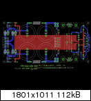
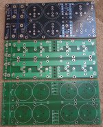
I connected Zobel's cap GND pin directly to the GND spade in the middle (red track), the same goes for the front-end's GND (also red track).
The bottom layer GND plane (blue plane) is for the 4 power caps now, note that I isolated Zobel's cap GND pin from the GND plane there. The speaker GND will be taken from the main PSU unit. I hope I am done with the GND thingy.
You might also notice that I moved the little cap beneath the largest cap to have good space for the GND spade so it will be the only component to be soldered beneath the PCB. In general, I wanted to have reasonable space for each spade, this is the main idea; at the same time have correct connections for the GND and NFB take-point. The image is large enough to enable members to comment. It is very important for me to hear your comments at this stage.
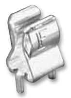
I am 2" close to finish the PCB, but still I need to know what the length of the European and American popular fuses is, I will only consider two lengths. I am willing to use a fuse holder like the one shown below, this will make both parties happier and fulfill all members wishes.
The bottom layer GND plane (blue plane) is for the 4 power caps now, note that I isolated Zobel's cap GND pin from the GND plane there. The speaker GND will be taken from the main PSU unit. I hope I am done with the GND thingy.
You might also notice that I moved the little cap beneath the largest cap to have good space for the GND spade so it will be the only component to be soldered beneath the PCB. In general, I wanted to have reasonable space for each spade, this is the main idea; at the same time have correct connections for the GND and NFB take-point. The image is large enough to enable members to comment. It is very important for me to hear your comments at this stage.
I am 2" close to finish the PCB, but still I need to know what the length of the European and American popular fuses is, I will only consider two lengths. I am willing to use a fuse holder like the one shown below, this will make both parties happier and fulfill all members wishes.
Attachments
The bottom layer GND plane (blue plane) is for the 4 power caps now, note that I isolated Zobel's cap GND pin from the GND plane there. The speaker GND will be taken from the main PSU unit. I hope I am done with the GND thingy.
The main caps will still have a charging current return through the ground spade back to the PS board, and this will be shared with the signal ground back to your star ground on the PS board. This is negating the advantage of a dual bridge.
It would be better to have the star ground on board, and not share that ground with charging currents. It would be beneficial to keep the main caps' grounds separate until the star point on the board. There remains a large distance between the ground return and each power supply input, making for a large loop area for these charging currents. If the grounds for each polarity of cap were brought out separately to the right side of the board, next to their paired polarity input spade, it would eliminate both of these issues. Of course, keeping the grounds of each polarity of cap separate on the main PS board would benefit the dual bridges, also.
Any "ground" spades on the right side of the board would not be true grounds, but returns to the separate windings of the transformer (assuming dual bridges). If a single bridge is used, each "ground" spade would return to the transformer center tap. The ground spade on the board should be the star ground, and signal ground. There should be a resistor connection between the signal ground on board, to the PS ground(s) on board.
Last edited:
Hi
Rudi and Metal, can you put more holes for input capacitor, in that case diferent type of caps could be mount there.
Amp and psu boards will have the same dimension?
For me, there is no problem what kind of fuse you will put on boards.
This is a very nice project and I'm sure that Rudi and Metal will make profesional boards with excelent design.
Marry Christmas and Happy New Year to all
Tome
Proper heat sink size
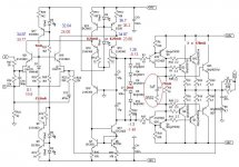
Based on the schematic, I'm making the assumption that this amplifier is rated at about 100W into 8 ohm speakers, with a 35VDC supply.
Power dissipation (Pd) for a class AB output stage is maximum at approximately 1/3 max output power. When operated at 1/3 power, dissipation is close to 46% for a real world class AB amp.
A 100-W/8-ohm amp will dissipate about 50W of heat at 1/3 rated power. Assuming you don't want heatsink temp to exceed 60C when operating at 1/3 output power, and if the ambient temperature is 25C, this corresponds to a heat sink thermal resistance of 0.7C/W. If you can tolerate temperatures above 60C, then your heat sink can be even smaller.
A 3 inch length of this heatsink, or something similar, should do the job, per board. In SI, this comes out to about 25 x 7.62 x 7.62 cm
Does anyone else concur with this approximation?
/Mason
No.Based on the schematic, I'm making the assumption that this amplifier is rated at about 100W into 8 ohm speakers, with a 35VDC supply.
100W into 8r0 requires 40Vpk into the load.
You cannot get anywhere near 40Vpk from a +-35Vdc supply.
Although this amplifier is not specified for 4ohm duty, I suspect it is capable of 100W into 4r0 and capable of driving a real 4ohm speaker.
where do you get your numbers from?A 3 inch length of this heatsink, or something similar, should do the job, per board. In SI, this comes out to about 25 x 7.62 x 7.62 cm
On third thoughts, with 6off 180W output devices this amp is probably good for 180W into 4r0 if you choose the ancillary components well.
Last edited:
heat sink SIZE
The main point of my post was to estimate the approximate heat sink size. I assumed that this amp is rated at 100W into an 8-ohm load, when powered in accordance with the schematic. The power transistors are supplied with +/- 34VDC. If the power is even less than 100W, as you indicate, the heat sinks can be sized even smaller!
The link I provided shows a heat sink rated at 0.8C/W/3". Based on a 100W, class AB amp, this should be large enough to dissipate the heat with a 3" length without burning your fingers off or frying the power transistors.
100W into 8r0 requires 40Vpk into the load.
The main point of my post was to estimate the approximate heat sink size. I assumed that this amp is rated at 100W into an 8-ohm load, when powered in accordance with the schematic. The power transistors are supplied with +/- 34VDC. If the power is even less than 100W, as you indicate, the heat sinks can be sized even smaller!
where do you get your numbers from?
The link I provided shows a heat sink rated at 0.8C/W/3". Based on a 100W, class AB amp, this should be large enough to dissipate the heat with a 3" length without burning your fingers off or frying the power transistors.
Last edited:
I cannot follow any of your logic.
If the schematic shows +-34Vdc, what do you expect the maximum signal available at the speaker terminals when driving 8r0 with a sinewave test signal?
I would expect <30Vpk and more probably <26Vpk.
Can you really expect a passive heatsink of ~ 3"high by 3"wide by 1"deep (15mm fins) to dissipate at the rate of 0.8C/W?
I see part of my error in reading your dimensions.
25 = 1", NO!
25 = centimetres !!!
250 = ~10"
25 = ~1"
25cm = ~ 10"
Last edited:
If the schematic shows +-34Vdc, what do you expect the maximum signal available at the speaker terminals when driving 8r0 with a sinewave test signal?
That is exactly my question. You are not being helpful.
Can you really expect a passive heatsink of ~ 3"high by 3"wide by 1"deep (15mm fins) to dissipate at the rate of 0.8C/W?
Are you blind? The heat sink is 10" long. Take the time to look at the diagram before you open your mouth.
/Mason
Last edited:
heat sinks...
I apologize for being harsh; I believe we may simply have a breakdown in communication. Happy Holidays and good will!
I ran the LTSpice simulation, located in the original FC-100 thread, and found the following max power outputs (before output sine started clipping)
Attached is the LTSpice simulation for your reference.
/Mason
Are you blind? The heat sink is 10" long. Take the time to look at the diagram before you open your mouth./Mason
I apologize for being harsh; I believe we may simply have a breakdown in communication. Happy Holidays and good will!
I ran the LTSpice simulation, located in the original FC-100 thread, and found the following max power outputs (before output sine started clipping)
- 60W @ 8 ohms
- 120W @ 4 ohms
- 1.2 C/W for 8 ohm loads
- 0.6 C/W for 4 ohm loads
Attached is the LTSpice simulation for your reference.
/Mason
Attachments
Gentlemen,
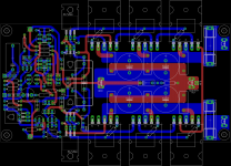
while I am waiting for Santa Claus to climb down the chimney, I like and show you a picture of METAL's and my progress:
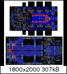
http://www.abload.de/img/both_1m7j9e.png
We will offer you these 2 PCBs:
1) the PSU (on the bottom of the picture; its size is: 170 x 85mm)
2) the AMP (on top of it; its size is 143 x 73mm)
The PSU includes:
1) the backend PSU
2) the frontend PSU (Mihai's shunt regulator)
We still have to settle upon several questions:
1) Where to combine the Backend-Power(VCC and VDD) - GND planes? On the AMP PCB, on the PSU PCB?
2) Where / how to connect the Backend-Power - GND to the Frontend-Power GND? On the AMP PCB, on the PSU PCB?
3) Where to connect Speaker's Return? To the AMP PCB, to the PSU PCB?
4) Where / how to connect the different GND-planes to the Power Earth / Safety - STARGROUND?
When these questions are answered, we are done.
I wish you all a happy Christmas - Rudi_Ratlos
the PSU (on the bottom of the picture; its size is: 170 x 85mm)
Do you happen to have a schematic of the PSU?
BTW, excellent job. I'm very much looking forward to having these boards in my hands!
/Mason
Capacitor holes
Hi Rudi,
To make your PSU boards more universal, could you please implement support for different capacitor pin-outs (like Peter Daniel on his PSU board).
http://www.diyaudio.com/forums/group-buys/140306-f5-pcb-group-buy.html
I wish you all a happy Christmas,
Bob03
Hi Rudi,
To make your PSU boards more universal, could you please implement support for different capacitor pin-outs (like Peter Daniel on his PSU board).
http://www.diyaudio.com/forums/group-buys/140306-f5-pcb-group-buy.html
I wish you all a happy Christmas,
Bob03
Attachments
Last edited:
zdr, make yourself a fresh cup of coffee, sit back, take a close look at the photo's on post #3, #4 and
the schematic on post #8 of Roender's amp thread and you will find the answer yourself.
Rudy has also answered your question in post #61 of this thread.
the schematic on post #8 of Roender's amp thread and you will find the answer yourself.
Rudy has also answered your question in post #61 of this thread.

- Status
- This old topic is closed. If you want to reopen this topic, contact a moderator using the "Report Post" button.
- Home
- Amplifiers
- Solid State
- Roender's FC-100 prototype and builder's thread