A wise man once said: "Ask two DIYers a question, and you will get 5 different answers."
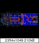
I had some time this morning and expanded the amplifier's PCB by a "mature" backend PSU on the right side.
This the result:
http://www.abload.de/img/topwview_with_psub9j9j.png
Is this what you want? It will be a very big (230 x 72 mm) PCB.
@ZDR: I changed indeed the footprints of the two TO-92 transistors in the yellow circle.
But these 2 transistors have not been thermally coupled on Mihai's original layout.
METAL and I decided to either offer you a PCB without any "PSU ingredients" at all or the PCB above.
What is your preference?
Best regards - Rudi_Ratlos
I had some time this morning and expanded the amplifier's PCB by a "mature" backend PSU on the right side.
This the result:

http://www.abload.de/img/topwview_with_psub9j9j.png
Is this what you want? It will be a very big (230 x 72 mm) PCB.
@ZDR: I changed indeed the footprints of the two TO-92 transistors in the yellow circle.
But these 2 transistors have not been thermally coupled on Mihai's original layout.
METAL and I decided to either offer you a PCB without any "PSU ingredients" at all or the PCB above.
What is your preference?
Best regards - Rudi_Ratlos

I counted five shrink wraps on this photo, plus one heatsink:
http://www.diyaudio.com/forums/soli...age-audio-power-amplifier-36.html#post1504684
http://www.diyaudio.com/forums/soli...age-audio-power-amplifier-36.html#post1504684
The PCB is not finished yet. We have to decide whether to offer the PCB with/out a PSU, the NFB track is not a problem, I have already decided what to do about it i.e. track. I had many thoughts indeed, and one of them is to create another PCB that will hold both the front PSU and the AMP PSU, what do you think?
The current AMP PCB that has a complete PSU is very long, 23cm, and this will create two problems, the first is that it is harder to ship, and the second is that the heatsink will have to be long enough to accommodate the 4 screws of the AMP PCB.
I don't think that we will use Miha's front PSU, it is better to use a shunt regulator, I believe we have a ready schematic for this one.
It’s a trade-off... (with or without PSU on board).
With the PSU on board, one only needs to add a transformer to get an amp channel running.
The amp PCB with PSU is indeed not small, but 230mm (length) is not too hard to handle if the PCB is mounted on the heatsink of a standard HiFi-2000 enclosure like this one (or heatsinks of similar sizes).
The shipment is another question, how much will the shipment cost be increased with this PCB size?
A separate PSU board on the other hand is more flexible and the idea of having a shunt regulator for the front-end (next to an unregulated amp PSU) is very appealing. My preference is this second option.
(with or without PSU on board).With the PSU on board, one only needs to add a transformer to get an amp channel running.
The amp PCB with PSU is indeed not small, but 230mm (length) is not too hard to handle if the PCB is mounted on the heatsink of a standard HiFi-2000 enclosure like this one (or heatsinks of similar sizes).
The shipment is another question, how much will the shipment cost be increased with this PCB size?
A separate PSU board on the other hand is more flexible and the idea of having a shunt regulator for the front-end (next to an unregulated amp PSU) is very appealing. My preference is this second option.
I don't think that we will use Miha's front PSU, it is better to use a shunt regulator, I believe we have a ready schematic for this one.
 Mihai's front end supply is a shunt regulator.
Hi Rudi, metal,
There are time when a wire jumper is superior to a trace laid out. This may be one of those cases. Whatever works to keep the actual signal runs short works the best.
My own opinion about the power supply - two PCBs. That way the boards will fit into varying styles of cases, and then there is also the opportunity to try other supplies. If someone wants, they could then insert a regulator PCB, so more options. Just an opinion.
Having built the Symasym V5.3, and the AAK release, I am extremely interested in building this version. I've been hanging back - watching. At any rate, once the design has been frozen and boards made, I may build one up. The previous releases did not disappoint, so I feel confident to recommend any of them. This one might be a game changer though. Any thoughts of reducing the output section size in order to offer a baby brother version? 50 wpc is often more than enough for most applications. It's the sound quality that is the goal. This would also be perfect for a speaker system that used an electronic crossover, allowing a lower powered amplifier to drive the tweeters. After this one is done of course!
-Chris
Last edited:
Afraid not.
The Roender Design requires 5 integrated diodes.
The 3 pair output stage provides 6 diodes. The one spare can be used to monitor output device temperature.
Once you have committed to a 3pair output stage, then why build a 50W amplifier?
The 3pair could easily drive a 4r0 load and a 4ohm speaker to at least 150W.
so design for 80W into 8r0 or 150W into 4r0.
Or use a lower voltage transformer and adjust the various components to ensure that the design current values are achieved at all operating conditions, eg. low mains voltage.
I would favor keeping one pair of main caps on board, and a separate or breakaway portion for any PS extras; i.e., second pair of caps and/or bridges.
This would shorten the board, provide on board main caps, and allow for keeping bridge(s) and first pair of caps, with their associated ripple currents, away from the circuit.
This would also provide a generic board for all variations of PS front end tastes. Provision for the series resistor/inductor between pairs of caps can be kept, if there is room, or provided on any separate or separable section.
I would still favor a positive and negative input connector pair close to each other for each main cap to keep twisted pair supply lines twisted up to the board, and a split ground plane between the main caps up to the star point.
BTW, nice effort!
Another option, if the bridge(s) and first pair of caps were on a separate board, is to use that board for the PS components for the supply for the input stage of the amp. Put BOTH input and output power supplies on the separate board.
Last edited:
Ferrari, Anatech: I am with you.
The PCB with onboard-PSU looks like a big whale, makes it hard to handle and since most of you already have beautiful power-supplies,
it would be "money poured down the drain".
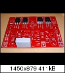
METAL and I will nevertheless offer to those of you, who do not have a power supply, a PCB based on these schematics: Greg's Web Site - DX PSU.
This PSU has been proven to work flawlessly, and I will even change its design to include 2 full bridge-rectifiers.
It will look like this:

http://www.abload.de/img/birger0022gjtf.jpg
And, of course, we will offer a shuntie for the frontend.
Mihai's AMP will have to compete with this one:
http://www.abload.de/img/joe003hekwo.jpg
This is a SYMASYM 5.3, Anatech, which I modified to include 2 pairs of beautiful NJW0281 / NJW0302 on the backend and a cap-multiplier for the frontend, and which I offered in a German group-buy several weeks ago.
You are welcome to visit me in Hamburg in spring 2012, when I will perform a "shootout" between Mihai's RMI FC-100 and Michael's SYMASYM.
Best regards - Rudi_Ratlos
The PCB with onboard-PSU looks like a big whale, makes it hard to handle and since most of you already have beautiful power-supplies,
it would be "money poured down the drain".
METAL and I will nevertheless offer to those of you, who do not have a power supply, a PCB based on these schematics: Greg's Web Site - DX PSU.
This PSU has been proven to work flawlessly, and I will even change its design to include 2 full bridge-rectifiers.
It will look like this:

http://www.abload.de/img/birger0022gjtf.jpg
And, of course, we will offer a shuntie for the frontend.
Mihai's AMP will have to compete with this one:

http://www.abload.de/img/joe003hekwo.jpg
This is a SYMASYM 5.3, Anatech, which I modified to include 2 pairs of beautiful NJW0281 / NJW0302 on the backend and a cap-multiplier for the frontend, and which I offered in a German group-buy several weeks ago.
You are welcome to visit me in Hamburg in spring 2012, when I will perform a "shootout" between Mihai's RMI FC-100 and Michael's SYMASYM.
Best regards - Rudi_Ratlos
YES, but there are better ones around.
Audibly better in this application? Or at least simulates better with this amp, enough so that a difference can be seen at the amp output?
I would suggest that tight coupling of the front end supply to the amp is probably more important for real life performance, than reaching for the nth degree of frequency response at the output of the regulator.
Sheldon
You are welcome to visit me in Hamburg in spring 2012, when I will perform a "shootout" between Mihai's RMI FC-100 and Michael's SYMASYM.
@Rudi&Metal: If you would like to discuss Mihai's design, maybe you should consider doing it in RMI-FC100 thread. We are derailing this one into something I do not like too much, and would probably dislike even more if I was the designer of FC100. I have a great respect for Mihai's work, and would not want to end up building Symasym, FetZilla or lawn mower with FC100 boards from this thread. I don't know about the rest of the guys, but unless PCBs respect the original proven and tested design, I think I will pass for now.
Sorry if I am getting too sensitive about all this, I still think you guys are doing a great job
Hi zdr,
I referenced the Symasym purely to explain a related design that I thought filled a certain power class. No direct comparison was intended, although I have built these earlier designs. They are popular enough to make a valid reference point. What I am discussing is a similar or near identical design for a lower powered cousin.
If I wished for a Symasym, I'd have simply built another. Relax.
Hi Andrew,
No one said that the same bias network must be used. In fact, a Vbe multiplier that used a pair of internal diodes would probably work great. All you need is a fast reflection of temperature. Given the close matching these devices have, it would be a safe assumption those other die will be very close to the temperature you are monitoring.
Don't look for reasons "why not". Look for ways to move forward.
-Chris
Hi Rudi,
Thank you for the invitation. I can't make it, but I would have really enjoy meeting with you. You and Metal have done some fine work here. I would be interested in what you find in comparing the two amps. This one looks like it should out-perform the Sym..... I don't think I'm allowed to say the name here.
I really love the NJW0281 and NJW0302 as well - you may have guessed. I am a huge fan of this line of output transistors, and also the MJW series (without the diode). I also think it's important to realize that you only need a couple devices with the sensing diode, the others can be straight transistors. I've been waiting for someone to show a design that wasn't straight out of the app note as far as the bias circuit was concerned.
If you have some info on your modification done to the Sym.... , would you be willing to share it with me?
So back to the design at hand. Front end regulation is the "secret sauce" that can make these designs special. I am anxious to see this design finalized. It looks extremely promising.
-Chris
I respect your sentiments, ZDR, but - at the same time - like to say: I am different from you.
I am a very pragmatic type of person.
I have DIYed a lot of AMPs so far, have been listening to their sound, tried to improve it (if possible) by very small changes,
(adding a CAP-multiplier to the frontend-power supply of Michael Bittner's SYMASYM, integrating a PSU on Carlos Mergulhao's DX BlameES, ...),
I have never changed the inherent schematics of an AMP, but made my little progresses available to the DIY community.
Did you ever listen to Carlos' DX BlameES with big SANKEN transistors on the output, to Michael's SYMASYM driving a pair of TO-3 or TO-3P?
If not: I understand, why you will withdraw from this thread.
As I told in post #1 of this thread, I felt very appealed to Mihai's implementation of an amplifier.
I will not change any single track or component of Mihai's design, but feel free to offer to the DIY community a layout that does not have
any "PSU ingredient on-board" (on the right side of the PCB) at all.
I will offer - on the other hand - a proven backend- and frontend (Mihai's shuntie) power supply.
So: what?
I will of course - I am a pragmatic type of person - compare the sound of Mihai's RMI FC-100 to Carlos' DX BlameES and Michael's TO-3P SYMASYM or ... and will report the feedback.
May I not?
Best regards - Rudi_Ratlos
Guys, calm down please! There is no FC100's cult here
I'm more than glad that Rudi and Metal wanna compare my design with other very popular at diyAudio. Let's the battle begin!
Anatech, the RMI-FC100 biasing schematic is not implemented strait from ONsemi app note because they ignored the differences between BJT and diode thermal coefficients.
I'm more than glad that Rudi and Metal wanna compare my design with other very popular at diyAudio. Let's the battle begin!
Anatech, the RMI-FC100 biasing schematic is not implemented strait from ONsemi app note because they ignored the differences between BJT and diode thermal coefficients.
Hi zdr,
"proved" doesn't necessarily mean perfect. If you add "im" to "proved", it becomes improved. Don't we like improved stuff?
Calm down, no need to consider changing as a disrespect to the original Amplifier designer.
Don't forget that we like you and want you with us in this thread :- )
Hi Sheldon,
There is a better design, but we will not discuss it in this thread. Rudi has already stated that we will not enforce serious changes at this stage. Forgive my loud thinking.
Today I will try to post an image for the final amp PCB. I still must work on the front PCB and the PSU PCB.

- Status
- This old topic is closed. If you want to reopen this topic, contact a moderator using the "Report Post" button.
- Home
- Amplifiers
- Solid State
- Roender's FC-100 prototype and builder's thread