I waited for about 10 minutes and then measured the emitter-resistor voltage drop for every resistor for about 5 seconds
and I write down the lowest and biggest value that I have measured during the 5 second interval.
The value of the trimm-potentiometer is adjusted to 168 Ohm.
Q3 - NJL0281: 17.9 - 18.3 mV
Q12 - NJL0281: 18.2 - 18.6 mV
Q25 - NJL0281: 17.9 - 18.3 mV
Q27 - NJL0302: 19.5 - 19.9 mV
Q5 - NJL0302: 17.2 - 17.7 mV (the internal diode short)
Q20 - NJL0302: 18.4 - 18.9 mV (bypassed by layout)
I will measure again in 30 minutes, when everything is really settled.
But the tendency is given in the values above.
Best regards - Rudi
Last edited:
I have a scope and checked for oscillations on the output and on capacitor C1 and C7.
I did not see any oscillation.
But I have not yet connected any load to the output.
Best regards - Rudi_Ratlos
P.S. Have a look at the beautiful sine wave the AMP is showing on the output - Post #226.
I did not see any oscillation.
But I have not yet connected any load to the output.
Best regards - Rudi_Ratlos
P.S. Have a look at the beautiful sine wave the AMP is showing on the output - Post #226.
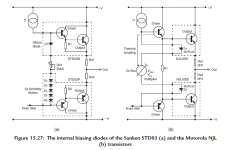
I found this interesting image (see below) in Dr. Self's book, Chapter 15: "Thermal Compensation and Thermal Dynamics".
In this chapter Dr. Self compares (amongst others) the behaviour of the internal biasing diodes of SANKEN STD03
and Motorola (OnSemi) NJL transistors.
Interesting for me to see: in case of NJL transistors Dr. Self suggests the thermal coupling to be done by using 2 internal diodes
and 2 VBe multipliers, which is in effect a 4-diode string.
Maybe that my 4-diode string is as valid and safe as the 5-diode string that Mihai implemented in his original design.
Maybe that a 5-diode string can only be achieved when the components are extremely well matched or - by chance.
I am curious about ZSAUDIO's results of his prototype build.
I sent him a pair of PCBs yesterday.
In the meantime I will go on and test my build under the aspect of thermal compensation.
Best regards - Rudi_Ratlos
P.S. @POOGE: I am using a 100 HMz Tektronix 465B oscilloscope.
Attachments
Hello Rudi,
i hope to get the pcb's this week and start to assemble and we'll see if i have the same issue.
I matched the NJL's and got similarly tight pairs like Mihai. I've got the groups from 25-25 pieces.
It would be good if you could do some thermal test of your amp. If my memory serves OS (Ostripper) made some test on it to use a hair-drier to warm up the heatsink and watch for Ibias change. Maybe some more experienced forum members can give us some hints how to do it in the proper way and how to deal with the results.
But i think if your amp behaves well ( sinus, square, THD, clipping and so on) and sounds good to you i would not worry about it.")
Best Regards,
zsaudio
i hope to get the pcb's this week and start to assemble and we'll see if i have the same issue.
I matched the NJL's and got similarly tight pairs like Mihai. I've got the groups from 25-25 pieces.
It would be good if you could do some thermal test of your amp. If my memory serves OS (Ostripper) made some test on it to use a hair-drier to warm up the heatsink and watch for Ibias change. Maybe some more experienced forum members can give us some hints how to do it in the proper way and how to deal with the results.
But i think if your amp behaves well ( sinus, square, THD, clipping and so on) and sounds good to you i would not worry about it.
Best Regards,
zsaudio


What is the voltage across the VR? ~400mVdc?
What is the resistance of the VR?
What is the current flowing through the VR?
If "VR" is variable resistor, these questions have been answered.
Andrew,
the voltage drop across the VR is 380mV.
Its current value is 162 Ohm.
(The value of 162 Ohm sets the voltage dropping across an emitter resistor to about 18 mV).
The current flowing through VR is 2.3mA then.
I will measure the pre-driver- and driver-base voltages in a minute.
Best regards - Rudi
the voltage drop across the VR is 380mV.
Its current value is 162 Ohm.
(The value of 162 Ohm sets the voltage dropping across an emitter resistor to about 18 mV).
The current flowing through VR is 2.3mA then.
I will measure the pre-driver- and driver-base voltages in a minute.
Best regards - Rudi
- Status
- This old topic is closed. If you want to reopen this topic, contact a moderator using the "Report Post" button.
- Home
- Amplifiers
- Solid State
- Roender's FC-100 prototype and builder's thread