thank you.Oh, my mistake it's 2SD1273!
Short form spec from datasheetarchive:
Surprisingly Vce(sat) is tested at only 40 hFE, however it will gladly do the same with much less base current. It starts to look like a FET with Vgs(th) = Vbe, in that you hardly need any current to drive it -- enough that, whatever peak capacity a gate drive source would supply (even logic level), it's more than enough to turn this thing on.
Tim
2SD1273/2SD1273A - hFE Rank classification:
Q: hFe = 500 to 1000
P: hFE = 800 to 1500
O: hFE = 1200 to 2500
The outline is TO220F.
http://www.datasheetcatalog.org/datasheet/panasonic/2SD1273A.pdf
http://www.datasheetcatalog.org/datasheet/panasonic/SJD00065BED.pdf
Are there also an TO220 version sourced from the same process in a non isolated outline ??
In a 2007 article I can't find, Bob Pease pointed out that as transistor beta increases the transistor mu decreases. As the beta increases the Hre increases (becomes worse) and the early voltage decreases. Mu is the inverse of Hre and the theoretical maximum voltage gain is the early voltage divided by the thermal voltage. High beta isn't all good.
mean you this author?In a 2007 article I can't find, Bob Pease pointed out that as transistor beta increases the transistor mu decreases. As the beta increases the Hre increases (becomes worse) and the early voltage decreases. Mu is the inverse of Hre and the theoretical maximum voltage gain is the early voltage divided by the thermal voltage. High beta isn't all good.
Bob Pease - Wikipedia, the free encyclopedia
http://www.eeweb.com/spotlight/interview-with-bob-pease
Last edited:
Yes, that's him. I think his article was in EDN magazine in late 2006 or early 2007, but I can't find it. If I recall, he said that too much beta would adversly affect the transistor voltage amplification. I emailed him requesting an explanation because I had never heard that before. He explained that the higher the beta, the lower the mu. If you have ever seen a superbeta transistor on a curve tracer, the early voltage is very low.
perhaps the article is mentioned in one of the TOC's aboutYes, that's him. I think his article was in EDN magazine in late 2006 or early 2007, but I can't find it. If I recall, he said that too much beta would adversly affect the transistor voltage amplification. I emailed him requesting an explanation because I had never heard that before. He explained that the higher the beta, the lower the mu. If you have ever seen a superbeta transistor on a curve tracer, the early voltage is very low.
2007 Print Archives | EDN
or
2006 Print Archives | EDN
Unfortunatly only from this year there are to find cover images of this magazine about
2011 Print Archives | EDN
here a photo galerie of the author from this article:
http://www.edn.com/blog/Anablog/41166-A_Bob_Pease_photo_gallery.php
Last edited:
I think the article may be in ED not EDN, but I can't find it.
Author : Bob Pease
Author : Bob Pease
Found this, but I still can't find the article. It has to be there somewhere.
www.electronicdesign.com/article/power/bob-s-mailbox18153.aspx
www.electronicdesign.com/article/power/bob-s-mailbox18153.aspx
Last edited:
Finally found it. I looked all afternoon for this.
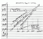
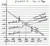
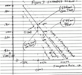
What's All This V<sub>BE</sub> Stuff, Anyhow? (Part 2)
What's All This V<sub>BE</sub> Stuff, Anyhow? (Part 2)
Thank you very much for your efforts to find this paper.Finally found it. I looked all afternoon for this.
What's All This V<sub>BE</sub> Stuff, Anyhow? (Part 2)
Part 1 you will find about:
What's All This VBE Stuff, Anyhow?
Best of Bob Pease - overview
The Best of Bob Pease
Book "Analog Circuits" read samples:
Analog circuits - Bonnie Baker - Google Bücher
Attachments
Last edited:
In a 2007 article I can't find, Bob Pease pointed out that as transistor beta increases the transistor mu decreases. As the beta increases the Hre increases (becomes worse) and the early voltage decreases. Mu is the inverse of Hre and the theoretical maximum voltage gain is the early voltage divided by the thermal voltage. High beta isn't all good.
Can one say, that therefore darlingtons often the better choice?
Early voltage of the here showed hugh Hfe types is always small.
Where in the BjT small signal transistor datasheets I find the parameter "Hre" (as you written) and Hrb (as to read in this paper) ??
by JFET transistor is mu = gm/Yfs.
http://www.kennethkuhn.com/students/ee351/jfet_basics.pdf
hfe = foward current transfer ratio (dimensionless value)
Yfs Forward Transfer Admittance (mS)
gm = transconductance gain (drain current divided by gate voltage)
about
ECE Formulas and Equations - ECELab.com
I read:
hfe = ic / ib; hFE = Ic / Ib where hfe/hFE are the ac and dc forward current transfer ratios, resp., ic and Ic are the ac and dc collector currents, ib and Ib are the ac and dc base currents;
Gm = ic / Vbe where Gm is the mutual conductance, ic is the ac signal collector-emitter current, and vbe is the base-emitter voltage; note: voltage gain G = Gm x R-load
hie = hfe / Gm where hie is the input resistance, which also equals the base input voltage divided by the base current.
Perhaps about
http://www.zen22142.zen.co.uk/Theory/tr_model.htm
there is the answer
Last edited:
> How do these devices compare with regard to Early Voltage to lesser DC gain devices of similar Vceo?
I'm not sure.
Basic junction theory suggests a trade-off between current gain and square of breakdown voltage. That is, assuming you had a good plan for hFE=200 at 25V, you could vary the junction and get these other parts:
hFE Vceo
50 400V
100 100V
200 25V
400 6V
800 1.5V
In real parts we don't get quite this relation, because actual-part breakdown is dominated by "sharp corners" in the geometry and the diffusion process offers only limited control of corner radii. But the trend is good: 300V transistors tend to have lower current gain, and Widlar's LM108 opamp got incredible current gain from input devices with very low breakdown. Andy Grove's book Physics and Technology of Semiconductor Devices gets into this more.
> the theoretical maximum voltage gain is the early voltage divided by the thermal voltage.
Yeah, that's one way to look at it. A good insight.
Of course a cascode breaks this trade-off. That's how the LM108 worked.
> using a super-beta driven by a tube because small signal tubes don't like to drive into the relatively low impedance of a regular BJT
A single transistor is generally not a great amplifier. Both Cherry/Hooper and Cowles (in very different ways) teach the use of pairs and other several-device schemes.
Note that a cascade of hFE=100 parts gives current-gain of 10,000, far beyond any single device. If transistors were expensive... but they aren't.
In a 2007 article I can't find, Bob Pease pointed out that as transistor beta increases the transistor mu decreases. As the beta increases the Hre increases (becomes worse) and the early voltage decreases. Mu is the inverse of Hre and the theoretical maximum voltage gain is the early voltage divided by the thermal voltage. High beta isn't all good.
While this is true youll find that in audio circuits it has many advantages. As in all circuits trade offs have to be made and the use of these super beta devices has many advantages that overwhelm negative tradeoffs.
In LTP s they reduce input bias currents and this has several positive effects. Here is a list of advantages :
Reduction of input offset voltage.
Reduction in input current distortion when input is fed from higher source resistances as usually happens with long cable runs, volume controls and preamp / sources that dont have very low output impedances.
Higher ripple rejection.
For the subjective guys the lower early voltage will cause higher second harmonic distortion and one can manupulate the specrum a bit and keeping all the above advantages.
Disadvantages:
In the case that the super beta has to be cascoded due to insuficient VCE, common mode distortion will increase and may become problemsome at especially high frequencies but this only happens when the closed loop gain is very small, say 1 to 10 X. In power amps with 20 X and up gain this factor is of very little or minute significance. For preamps it has to be kept in mind but then again as preamps usually run off lower rails, cascoding wouldnt be needed anyway. The cure for the case with poweramps with cascodes if you feel that "very little or minute significance" is too much for you to bear, is the use of cascodes with the base referenced to the LTP tail instead of the usual biasing from the rails. This is a very minor disadvantage as higher voltage superbeta transistors are available.
What is the base diffusion capacitance like in those transistors? I would imagine that it would be lower than with normal transistors because it's value is related to base current.
I have to say that base diffusion capacitance is a shocker when you first encounter it, the values are just so high (even up to 1000pF). And it's like "and you thought MOSFET's were bad".
I have to say that base diffusion capacitance is a shocker when you first encounter it, the values are just so high (even up to 1000pF). And it's like "and you thought MOSFET's were bad".
What is the base diffusion capacitance like in those transistors? I would imagine that it would be lower than with normal transistors because it's value is related to base current.
I have to say that base diffusion capacitance is a shocker when you first encounter it, the values are just so high (even up to 1000pF). And it's like "and you thought MOSFET's were bad".
Im no expert in the diffusion process but seems to me similar to better to transistors with standard hfe. A good indication would be the ft (influence of emiter base junction capacitance). It is sometimes better, sometimes comparable and sometimes just a little worse off.
I have not downloaded the datasheets from post 34. I will do later.
I have found that many of the more generally known higher hFE devices tend to have an fT~100MHz.
Whereas higher fT tends to belong to lower hFE.
It appears as a trade off of parameters. A bit like very high Vce0 generally compromises the other parameters.
I have found that many of the more generally known higher hFE devices tend to have an fT~100MHz.
Whereas higher fT tends to belong to lower hFE.
It appears as a trade off of parameters. A bit like very high Vce0 generally compromises the other parameters.
Single transistors (i. e. without internal darlington topology) with very high hfe up to 3000 are not often to find.
Here some examples: ...
Which benefits are there in opposite to a darlington topology ?
Are there particularly suited for certainly amplifier topologies ?
Which certain applications are there, where normal darlingtons are not a good choice ?
Thank you for comments
i have always wondered if a nice Vas (for instance a high performance discrete op-amp) boosted by a good powerful darlingtons push-pull output stage could not be enough for a very decent sounding mid-power amp
A push-pull with these https://www.mouser.it/datasheet/2/308/MJ11012_D-1811348.pdf for instance
Last edited:
- Home
- Amplifiers
- Solid State
- Questions about Transistors with high beta (hfe) up to 3000 without Darl.-Topology


