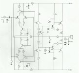
moscheft: what is wrong with Q14 ? :S
the low ohm is because i have an sub with two 4 ohms subs, and these are in parallel and i need to disamble the sub if it shall goes in 4 ohms. how many output devices is need for 1 ohm ? i had made one of these class ab amp before with +-40 volt rail and smaller output deviceses and i also just gave 65 watt whit low thd. but now i will try a bigger one. and because i have a serios transformer laying with many bigs caps and biig diode rectifier. i was building an class t amp , an amp 7 from 41hz.com but it played fm noise with an +-52 test rail, and my first time i mounted the 58+- rail it blows up, but it was because a lm317 was shorted so the 10 volt supply was 28 volt, all fets blows , the tripath ta3020 chip blows up and 5 caps blows up, i dont know if i try it again some time, but for now it is laying in the corner
amtech, what will the caps do diffrence ? are u meaning that i shall add a 47 uf cap or 100 uf between the resistor and ground ?
yes, add a 47uf in front of this 1k resistor to ground
If you don't see it, but Q14,20,21,22,23 are wrong wired.
The emitter must wired at positive voltage.
I agree, there! npn's ie 2sc5200 pos rail and pnp's to the neg rails
this is the org schematics from the amp that i had build before, it runs +/- 40 volt and delivers 50 watt.

This is the new schematics, will this look better ? i am planing to drive it in 4 ohms, or ells it shall have 24 output transistores for 1 ohm. i have found some fault in the old ones i have edited.
View attachment Forstærker.ms11.pdf

This is the new schematics, will this look better ? i am planing to drive it in 4 ohms, or ells it shall have 24 output transistores for 1 ohm. i have found some fault in the old ones i have edited.
View attachment Forstærker.ms11.pdf
I would agree with Andrew, in-relation to the above suggestions... adding a thermal cut is not enough to protect this amplifier with the amount of power transistor's your thinking of adding in to this build, also include speaker relay protection circuit there's plenty of circuit designs or you can buy ready made kits.. These unit's give soft start and switch the load via a relay and will disconnect in case there's large dc on the amp's o/p.
off course i will add fuses on the ac and on the dc and on the speaker output, i will also add a core that messure the current and telling it to a arduino board and if the current is to high or the temp goes to high the dc relay cuts and also speaker relay cuts  will all the other parts off the amp work ?
and i will add this circuit to the powersupply
View attachment PSU1_SS_schematics.pdf
what do you mean with sorted the schematic ? the last schematic i had posted is that i mean will work ?
yes i had tried but cant figure out why it is so diffrend than others, the picture i had posted before is the amp i have had working for 1 year without problems, so i cant understand why it is diffrence. the design is a old design, that is designed by bencar, but his site dont exsist anymore
yes i had tried but cant figure out why it is so diffrend than others, the picture i had posted before is the amp i have had working for 1 year without problems, so i cant understand why it is diffrence. the design is a old design, that is designed by bencar, but his site dont exsist anymore
- Status
- This old topic is closed. If you want to reopen this topic, contact a moderator using the "Report Post" button.
- Home
- Amplifiers
- Solid State
- High Power Amplifier