I have a Luxman R-117 receiver with blown-up right channel that I’m trying to fix. I think I found what’s wrong with it but I don’t know why this problem occurred in the first place and how to find it.
This is the former parts unit that I got as non-working: upon power-up it blew fuse. Unplugged both amp boards- powers on OK. Tested output transistors and found that two in the right channel, 2SC3281 and 2SA1302, are shorted. More diagnostics showed that two small current limiting transistors, 2SB631K and 2SD 600K, are shorted too (Q544 and Q528, sorry I can't attach the file with schematics since site is not working well; it s on vinylengine or send me a message). The two big current limiters, Q546 and Q530, are OK as are diodes in the 74V rail, D520, D526, D530 and D532.
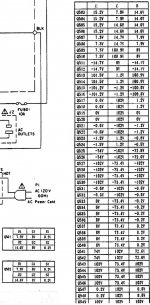
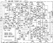
What bothers me is when I soldered out the four output transistors and measured voltages at their terminals on PCB, voltages at bases of all four of them were way out of expected: +10.6 to +11.7 volts instead of +0.2 or -0.2 volts. The voltage at collectors was + or – 101 volts instead of + or – 73 but this could be explained since current limiters are shorted and +/- 102 V goes directly to collectors. Voltages at emitters were 7-15 mV which I believe is within specs.
I tested with diode tester a pre-driver Q514, drivers Q518 and Q522, and “post-drivers” Q532 and Q548. Tests were done in-circuit and none of the transistors was found shorted. Resistors connected to bases of outputs, i.e. R580, R582, R584 R602, R604 and R606 are OK too.
Could this wrong voltage at bases of output transistors be an indication of a problem elsewhere? After all, outputs and current limiters were shorted for a reason. What might it be? Where else should I look?
Any suggestions will be most appreciated.
This is the former parts unit that I got as non-working: upon power-up it blew fuse. Unplugged both amp boards- powers on OK. Tested output transistors and found that two in the right channel, 2SC3281 and 2SA1302, are shorted. More diagnostics showed that two small current limiting transistors, 2SB631K and 2SD 600K, are shorted too (Q544 and Q528, sorry I can't attach the file with schematics since site is not working well; it s on vinylengine or send me a message). The two big current limiters, Q546 and Q530, are OK as are diodes in the 74V rail, D520, D526, D530 and D532.
What bothers me is when I soldered out the four output transistors and measured voltages at their terminals on PCB, voltages at bases of all four of them were way out of expected: +10.6 to +11.7 volts instead of +0.2 or -0.2 volts. The voltage at collectors was + or – 101 volts instead of + or – 73 but this could be explained since current limiters are shorted and +/- 102 V goes directly to collectors. Voltages at emitters were 7-15 mV which I believe is within specs.
I tested with diode tester a pre-driver Q514, drivers Q518 and Q522, and “post-drivers” Q532 and Q548. Tests were done in-circuit and none of the transistors was found shorted. Resistors connected to bases of outputs, i.e. R580, R582, R584 R602, R604 and R606 are OK too.
Could this wrong voltage at bases of output transistors be an indication of a problem elsewhere? After all, outputs and current limiters were shorted for a reason. What might it be? Where else should I look?
Any suggestions will be most appreciated.
you need to trouble shoot the amp stage by stage ...in your case this is a class G amplifier meaning that its switching rail voltage depenting on the output needs
this can be quite tricky to work with since too many circuits that are involved with the supply but also with current limiting are connected together
if you have no obvious damage a better approach will be in a way to isolate the high rail voltage and current limiting circuits to work with the amplifier in class AB conditions ...stabilize his section first and then look to the other sections such is the current limits and high rail symmetrical switch and power parts
this one will not be easy
kind regards
sakis
Luxman Repair
I am not a tech, but I have repaired one of my R117s also with a blown right channel as I recall. If you need help I can tell you of my experiences, what I found and what I did. The amplifier section is working great now, but it is uncalibrated, no time. I still need to work on the preamp section, it also has issues with one channel that I think is going to be on the input selector board when all is said and done. BTW once the amp is up and running I would try a TP117 to run it instead of the internal pre. The amp section is way better than the preamp section and this pre is very, very good. I have some pretty good mono and stereo amps, and preamps as well, and they are pretty much in their boxes most of the time and this is the combo I listen to.
I am not a tech, but I have repaired one of my R117s also with a blown right channel as I recall. If you need help I can tell you of my experiences, what I found and what I did. The amplifier section is working great now, but it is uncalibrated, no time. I still need to work on the preamp section, it also has issues with one channel that I think is going to be on the input selector board when all is said and done. BTW once the amp is up and running I would try a TP117 to run it instead of the internal pre. The amp section is way better than the preamp section and this pre is very, very good. I have some pretty good mono and stereo amps, and preamps as well, and they are pretty much in their boxes most of the time and this is the combo I listen to.
The schematics and voltage tables are now attached. Sorry for the inconvenience.
All:Thank you very much for your help and advices. I will do some more troubleshooting and will report back..or ask for help again.
All:Thank you very much for your help and advices. I will do some more troubleshooting and will report back..or ask for help again.
Attachments
Luxman Repair, path of desctruction
I dug out the spreadsheet with the R117 repair info and provide the below list as it may be helpful. I bought this unit as non-working for the purpose of restoration or to scavenge the parts for another unit if I failed to get it running. I was right it was the right channel that was blown. The below list of damaged items is what I like to term the Path of Destruction.
Q538,2SC3281Shorted
Q540,2SC3281Shorted
Q534,2SA1302Shorted
Q518,2SC3467Blown
Q522,2SA1370Blown
R602,4.7ohm 1/2 watt F.R.Open
R604,4.7ohm 1/2 watt F.R.Open
R616,330ohm 1/2 watt F.ROpen
R608,.22 ohm 5 watt C.E.Open
R584,470 ohm 1/4 watt F.R.Open
R562,1K ohm 1/4 watt F.R.Open
D506,1S1588Shorted
D508,1S1588Shorted
ZD502,Zener 1/2W 12.2V ZD50-122Shorted
ZD504,Zener 1/2W 12.2V ZD50-122Shorted
Using your basic VOM and a capacitance tester I got to the above list by starting at each of the power transistors leads and working my way out along the circuit paths. I sometimes had to de-solder some components to test them properly. Once I had my list I went shopping for the parts. If I had to make a guess, remember I am not a tech, as to what it was that blew up this channel. I would have to say that I have strong feelings on R608 as the culprit.
You can look over the above for now and see if it is helpful. I will try and put together a list of sources for the parts I replaced. I kept to the original OEM spec and name brands as best I could.
I dug out the spreadsheet with the R117 repair info and provide the below list as it may be helpful. I bought this unit as non-working for the purpose of restoration or to scavenge the parts for another unit if I failed to get it running. I was right it was the right channel that was blown. The below list of damaged items is what I like to term the Path of Destruction.
Q538,2SC3281Shorted
Q540,2SC3281Shorted
Q534,2SA1302Shorted
Q518,2SC3467Blown
Q522,2SA1370Blown
R602,4.7ohm 1/2 watt F.R.Open
R604,4.7ohm 1/2 watt F.R.Open
R616,330ohm 1/2 watt F.ROpen
R608,.22 ohm 5 watt C.E.Open
R584,470 ohm 1/4 watt F.R.Open
R562,1K ohm 1/4 watt F.R.Open
D506,1S1588Shorted
D508,1S1588Shorted
ZD502,Zener 1/2W 12.2V ZD50-122Shorted
ZD504,Zener 1/2W 12.2V ZD50-122Shorted
Using your basic VOM and a capacitance tester I got to the above list by starting at each of the power transistors and working my way out along the circuit paths. I sometimes had to de-solder some components to test them properly. Once I had my list I went shopping for the parts. If I had to make a guess, remember I am not a tech, as to what it was that blew up this channel. I would have to say that I have strong feelings on R608 as the culprit.
You can look over the above for now and see if it is helpful. I will try and put together a list of sources for the parts I replaced. I kept to the original OEM spec and name brands as best I could.
Basic test on the transistors
Q546Q538Q540D532D530Q536Q534Q5302SA1302 R *J72SC3281 R *J72SC3281 R *J72SA1302 R *J72SA1302 R *J72SC3281 R *J7LeadsPNPNPNNPNPNPPNPNPN P+=>N-B C EB C EB C EB C EB C EB C EB===>C10010540.4B===>E10010542.2C===>E100101C===>B461.200474.401E===>B492.200497.901E===>C100101hfe @10uA Vce3.2v New 130.660.960.341
I dug out the spreadsheet with the R117 repair info and provide the below list as it may be helpful. I bought this unit as non-working for the purpose of restoration or to scavenge the parts for another unit if I failed to get it running. I was right it was the right channel that was blown. The below list of damaged items is what I like to term the Path of Destruction.
Q538,2SC3281Shorted
Q540,2SC3281Shorted
Q534,2SA1302Shorted
Q518,2SC3467Blown
Q522,2SA1370Blown
R602,4.7ohm 1/2 watt F.R.Open
R604,4.7ohm 1/2 watt F.R.Open
R616,330ohm 1/2 watt F.ROpen
R608,.22 ohm 5 watt C.E.Open
R584,470 ohm 1/4 watt F.R.Open
R562,1K ohm 1/4 watt F.R.Open
D506,1S1588Shorted
D508,1S1588Shorted
ZD502,Zener 1/2W 12.2V ZD50-122Shorted
ZD504,Zener 1/2W 12.2V ZD50-122Shorted
Using your basic VOM and a capacitance tester I got to the above list by starting at each of the power transistors leads and working my way out along the circuit paths. I sometimes had to de-solder some components to test them properly. Once I had my list I went shopping for the parts. If I had to make a guess, remember I am not a tech, as to what it was that blew up this channel. I would have to say that I have strong feelings on R608 as the culprit.
You can look over the above for now and see if it is helpful. I will try and put together a list of sources for the parts I replaced. I kept to the original OEM spec and name brands as best I could.
I dug out the spreadsheet with the R117 repair info and provide the below list as it may be helpful. I bought this unit as non-working for the purpose of restoration or to scavenge the parts for another unit if I failed to get it running. I was right it was the right channel that was blown. The below list of damaged items is what I like to term the Path of Destruction.
Q538,2SC3281Shorted
Q540,2SC3281Shorted
Q534,2SA1302Shorted
Q518,2SC3467Blown
Q522,2SA1370Blown
R602,4.7ohm 1/2 watt F.R.Open
R604,4.7ohm 1/2 watt F.R.Open
R616,330ohm 1/2 watt F.ROpen
R608,.22 ohm 5 watt C.E.Open
R584,470 ohm 1/4 watt F.R.Open
R562,1K ohm 1/4 watt F.R.Open
D506,1S1588Shorted
D508,1S1588Shorted
ZD502,Zener 1/2W 12.2V ZD50-122Shorted
ZD504,Zener 1/2W 12.2V ZD50-122Shorted
Using your basic VOM and a capacitance tester I got to the above list by starting at each of the power transistors and working my way out along the circuit paths. I sometimes had to de-solder some components to test them properly. Once I had my list I went shopping for the parts. If I had to make a guess, remember I am not a tech, as to what it was that blew up this channel. I would have to say that I have strong feelings on R608 as the culprit.
You can look over the above for now and see if it is helpful. I will try and put together a list of sources for the parts I replaced. I kept to the original OEM spec and name brands as best I could.
Basic test on the transistors
Q546Q538Q540D532D530Q536Q534Q5302SA1302 R *J72SC3281 R *J72SC3281 R *J72SA1302 R *J72SA1302 R *J72SC3281 R *J7LeadsPNPNPNNPNPNPPNPNPN P+=>N-B C EB C EB C EB C EB C EB C EB===>C10010540.4B===>E10010542.2C===>E100101C===>B461.200474.401E===>B492.200497.901E===>C100101hfe @10uA Vce3.2v New 130.660.960.341
I did another round of testing and didn’t find any faulted components except those found before. Form all the components Retrex found damaged only one of Q538/Q540 and one of Q534/Q536 are shorted. I checked all electrolytes for shortages and found none.
That’s what I am planning to do (I am not a tech, so bear with me):
- order new output transistors from Mouser, MJL3281AG and MJL1302AG, substituting for 2SC3281 and 2SA1302, respectively.
- order the exact replacement for Q544, 2SB631K and Q528, 2SD600K, from B&D Enterprises. Should these be hFE matched?
- order replacements for Q532 and Q548, 2SA1516 and 2SC3907, from B&D Ent. They test OK at least in circuit but might be stressed by shorted outputs.
- get new emitter resistors, R608 and R610, since they could also be stressed. However, I didn’t source them yet. Any suggestions (3-pin, 0.22 Ohm, 5 W)?
Then, as Sakis suggested, “isolate the high rail voltage and current limiting circuits to work with the amplifier in class AB conditions” by not soldering back Q530, Q546 and new Q528/Q544. Solder in new outputs and test with the dumb bulb tester if Luxman powers up well. If yes, supply 1 kHz input signal with a generator and test the amp circuit with the scope. If amp is OK, solder in Q530, Q546, new Q528 and Q544 and repeat the scope test.
Does this sound as a good plan?
Hi kotofei,
No. This is not a good plan at all. I'll never understand why people who do not have the training or required equipment decide to take on the more powerful, higher quality items.
I'm all for trying to help people out, and gladly do so if there is a reasonable chance for success. Also, understand that with skilled repair people, like Sakis for example, there are a million important details that we don't even think about when we're working. We just know them and work on automatic. Things that are so painfully obvious to us that we would never consider anyone else to not know and understand these things. That is one reason that watching a skilled tradesman working seems like it's so darned easy to do what we're doing. As him how many years it took him to get to that level, and how many electronics courses or years in school to learn the basics. Even the selection of part type, and the mechanical skill used in soldering them, or bolting the transistors down. Most people, technicians, badly over-tighten transistors.
The light bulb tester is a really rough current limiter that does allow a fair amount of surge energy through at turn on. I disagree with the use, although it does function many times. It still is not the right way to "soft start" something. I can hardly wait until those damn bulbs are no longer available for purchase! That's about the only way to curtail this practice. I'm pretty tired of cleaning up these messes in my area.
What you need is a variable AC transformer that includes both a voltmeter and a current meter (analog please!). That and an intelligent servo to operate it (that would be you). A half decent DMM is required, and I'm talking about a meter that has two good decimal places in the mA scale. Maybe one decimal place in a pinch. That means you can read x.00 mA allowing the last digit to have a 5 count uncertainty at the worst. Although many people who don't have an oscilloscope will disagree, you need a real 'scope. Sound card things are useless - don't even consider trying. Even a 5 MHz unit will work okay, but not tube based construction. You need to use a soldering station with constant temperature and a grounded tip (changeable). These will set you back less than $100 and even sport a digital display.
If anyone isn't prepared to make that minimal investment in themselves, they do not have any business poking around inside anything. These items will typically last you well over 10 years before replacement time. My soldering station is well over 15 years old now and going strong, and it's one of those < $100 things.
Even experienced service technicians power up repairs gently while watching specific voltages and / or currents. A beginner should do no less as it's even more important they are careful.
I am wishing you success, but I'm hoping you amass the tools required to do the job first. Certainly you should bone up on how these output circuits work before diving in.
-Chris
Hi Chris,
I understand your frustration when "people who do not have the training or required equipment" screw it up and then bring to your shop to "cleaning up these messes". I wouldn't bring that Luxman to your shop, I promise.
I have most of the equipment you mentioned: a soldering station with constant temperature and replaceable tip, a real 100 mHz solid state scope and a Triplett 9045 true RMS multimeter that can read x.00 mA (and another less sophisticated). I also have some experience in fixing and upgrading audio gear, a basic electronic knowledge and a Ph.D. in another field so I probably could be considered an "intelligent servo".
The only piece of equipment I don't have is a variable AC transformer; however, this thing could be purchased. What I also don't have is an experience such as yours
Since you don't like my plan for dealing with this Luxman at all, you probably have some other formed in your head right away. What is it?
Thank you.
Hi kotofei,
No. This is not a good plan at all. I'll never understand why people who do not have the training or required equipment decide to take on the more powerful, higher quality items.
I'm all for trying to help people out, and gladly do so if there is a reasonable chance for success. Also, understand that with skilled repair people, like Sakis for example, there are a million important details that we don't even think about when we're working. We just know them and work on automatic. Things that are so painfully obvious to us that we would never consider anyone else to not know and understand these things. That is one reason that watching a skilled tradesman working seems like it's so darned easy to do what we're doing. As him how many years it took him to get to that level, and how many electronics courses or years in school to learn the basics. Even the selection of part type, and the mechanical skill used in soldering them, or bolting the transistors down. Most people, technicians, badly over-tighten transistors.
The light bulb tester is a really rough current limiter that does allow a fair amount of surge energy through at turn on. I disagree with the use, although it does function many times. It still is not the right way to "soft start" something. I can hardly wait until those damn bulbs are no longer available for purchase! That's about the only way to curtail this practice. I'm pretty tired of cleaning up these messes in my area.
What you need is a variable AC transformer that includes both a voltmeter and a current meter (analog please!). That and an intelligent servo to operate it (that would be you). A half decent DMM is required, and I'm talking about a meter that has two good decimal places in the mA scale. Maybe one decimal place in a pinch. That means you can read x.00 mA allowing the last digit to have a 5 count uncertainty at the worst. Although many people who don't have an oscilloscope will disagree, you need a real 'scope. Sound card things are useless - don't even consider trying. Even a 5 MHz unit will work okay, but not tube based construction. You need to use a soldering station with constant temperature and a grounded tip (changeable). These will set you back less than $100 and even sport a digital display.
If anyone isn't prepared to make that minimal investment in themselves, they do not have any business poking around inside anything. These items will typically last you well over 10 years before replacement time. My soldering station is well over 15 years old now and going strong, and it's one of those < $100 things.
Even experienced service technicians power up repairs gently while watching specific voltages and / or currents. A beginner should do no less as it's even more important they are careful.
I am wishing you success, but I'm hoping you amass the tools required to do the job first. Certainly you should bone up on how these output circuits work before diving in.
-Chris
R117 Testing
Again not a tech, but the Q528/Q544 would have me looking at the power supply board and verifying all PSB voltages are normal before putting power to the amp board. I think you can do this without having the board MP802 connection made. I seem to recall doing this.
I don't know the Q#s of the power transistors you found faulty so I can't look at other possible issues on my schematic. Also, although you probably don't have to, I always de-solder transistors when I test them. For no good reason other than it gives me peace of mind that I am testing what I want to test, and as an added task I check the hfe to make sure it is within spec. I replaced one power transistor because even though it tested ok in and out of circuit, the hfe was low with respect to the other transistors.
I did not find any blown caps in my testing as well. The transistors I used came from an ebay supplier who had a stash of "Original Equipment Manufacture" Toshibas and another ebay source for the newer 2SA1493/2SC5200 equivalents in case the "OEMs" were fakes. Before someone jumps onto the fake transistor soapbox, the word coming back on feedback from others who had bought the same was that they worked, for both sellers. I also read as much as I could find on the internet as to how to spot/test fakes. Still, it was a roll of the dice. I have run the "OEM" replacements hard through Magnepan speakers and they survived and sounded indestinguisable from the undamaged channel. The bad diodes and resistors I replaced with comperable spec quality components. High speed switching diodes for high speed switching. In some cases better quality, tolerance, higher watt metal film resistors for original carbon. I wanted to try and maintain the original sound of the unit if I could but hedge toward beefy components when possible.
For the R608 you cannot buy these I believe, well at the time I did the repair I couldn't. I got them in a user company to OEM Company sample request for testing purposes. I.E. I went through the compay I worked for and made an official request for samples to the German manufacturer. It cost a good deal of money just to ship the small sample lot that I received and I don't think the OEM company would sell to the public. If these tested out ok in your damaged board I would not replace them.
Again because I am not a tech my approach was to test and verify every component on the board, and source voltages too, before replacing the spent items and powering it up. I probably got lucky and it worked well right from the start and it continues to work well, less the preamp section as mentionded above. I do have a scope and some of the basic tools that Anatech mentions and do recomend at the very least a decent VOM with transistor/diode functions. I find a capacitance meter useful as well.
While you wait for your components to get in I would go over the entire board once again, just for peace of minds sake.
I did another round of testing and didn’t find any faulted components except those found before. Form all the components Retrex found damaged only one of Q538/Q540 and one of Q534/Q536 are shorted. I checked all electrolytes for shortages and found none.
That’s what I am planning to do (I am not a tech, so bear with me):
- order new output transistors from Mouser, MJL3281AG and MJL1302AG, substituting for 2SC3281 and 2SA1302, respectively.
- order the exact replacement for Q544, 2SB631K and Q528, 2SD600K, from B&D Enterprises. Should these be hFE matched?
- order replacements for Q532 and Q548, 2SA1516 and 2SC3907, from B&D Ent. They test OK at least in circuit but might be stressed by shorted outputs.
- get new emitter resistors, R608 and R610, since they could also be stressed. However, I didn’t source them yet. Any suggestions (3-pin, 0.22 Ohm, 5 W)?
Then, as Sakis suggested, “isolate the high rail voltage and current limiting circuits to work with the amplifier in class AB conditions” by not soldering back Q530, Q546 and new Q528/Q544. Solder in new outputs and test with the dumb bulb tester if Luxman powers up well. If yes, supply 1 kHz input signal with a generator and test the amp circuit with the scope. If amp is OK, solder in Q530, Q546, new Q528 and Q544 and repeat the scope test.
Does this sound as a good plan?
Again not a tech, but the Q528/Q544 would have me looking at the power supply board and verifying all PSB voltages are normal before putting power to the amp board. I think you can do this without having the board MP802 connection made. I seem to recall doing this.
I don't know the Q#s of the power transistors you found faulty so I can't look at other possible issues on my schematic. Also, although you probably don't have to, I always de-solder transistors when I test them. For no good reason other than it gives me peace of mind that I am testing what I want to test, and as an added task I check the hfe to make sure it is within spec. I replaced one power transistor because even though it tested ok in and out of circuit, the hfe was low with respect to the other transistors.
I did not find any blown caps in my testing as well. The transistors I used came from an ebay supplier who had a stash of "Original Equipment Manufacture" Toshibas and another ebay source for the newer 2SA1493/2SC5200 equivalents in case the "OEMs" were fakes. Before someone jumps onto the fake transistor soapbox, the word coming back on feedback from others who had bought the same was that they worked, for both sellers. I also read as much as I could find on the internet as to how to spot/test fakes. Still, it was a roll of the dice. I have run the "OEM" replacements hard through Magnepan speakers and they survived and sounded indestinguisable from the undamaged channel. The bad diodes and resistors I replaced with comperable spec quality components. High speed switching diodes for high speed switching. In some cases better quality, tolerance, higher watt metal film resistors for original carbon. I wanted to try and maintain the original sound of the unit if I could but hedge toward beefy components when possible.
For the R608 you cannot buy these I believe, well at the time I did the repair I couldn't. I got them in a user company to OEM Company sample request for testing purposes. I.E. I went through the compay I worked for and made an official request for samples to the German manufacturer. It cost a good deal of money just to ship the small sample lot that I received and I don't think the OEM company would sell to the public. If these tested out ok in your damaged board I would not replace them.
Again because I am not a tech my approach was to test and verify every component on the board, and source voltages too, before replacing the spent items and powering it up. I probably got lucky and it worked well right from the start and it continues to work well, less the preamp section as mentionded above. I do have a scope and some of the basic tools that Anatech mentions and do recomend at the very least a decent VOM with transistor/diode functions. I find a capacitance meter useful as well.
While you wait for your components to get in I would go over the entire board once again, just for peace of minds sake.
Hi kotofei,
You do have all that gear? Fantastic!! You have no idea how much that pleases me. I will apologize for assuming you didn't, it didn't sound like that from the previous posts. You also have experience working with PCB circuitry, another huge plus.
Okay, so I'll assume you also have troubleshooting experience and a logical approach to what you are doing. This is unusual for someone requesting help the way this unfolded. As for the emitter resistors, you can buy those from some of the repair parts jobbers. Some of the Ebay stores in the far east likely have them as well. Failing that, just buy the non-inductive resistors carried by Digikey (I think) that are the stand up type. Not pretty, but fine electrically. Normal WW 5 watt resistors are inductive, they can cause severe instability depending on the circuit and it's construction.
The transistors that On Semi has are extremely good. Use those. My own supplier I used for 15 years for Japanese parts closed his doors a while ago. We are both in the same boat as far as procuring parts is concerned.
Replacing transistors. Replace everything to the last defective part you find. Then replace one step further back. Also, replace the diff pair with a matched set. They will be damaged due to reverse bias across one. They will test fine usually, but the beta will be changed, and the damaged part may become more noisy. They are inexpensive, but you will need to buy about 10 ~ 20 of them to get good matches. Check the other channel while you're at it. A good match does reduce distortion, the reverse is also true. When testing transistors, check leakage C-E and C-B. Also, reject parts where the beta is way out from normal, high or low - the part is still bad. It also helps to heat parts up while watching leakage C-B, or even beta. This will catch most soft failures that can really ruin your day.
Matching transistors. For outputs, you can use a jig you assemble yourself. Something like the Heathkit IT-18 (or similar) is about the best for testing and matching outputs. You do have to keep the case temperatures the same. For matching signal transistors, another jig is the only sane way to accomplish this. Transistors are very sensitive to temperature, so you must take that out of the equation. I whipped up a simple jig for this, I'd be happy to give you the details. It works so well I've worn out the sockets again, and it's still all ugly built on perf board. Someone should design a PCB for it. Just give me a PM.
The variac can be purchased easily, please do that. You only need about 2 amperes normally, but a 5 ampere model might be the best. Hanging analog meters on it is easy enough. For this, digital meters are not required and too hard to read as things change. Analog meters will allow you to watch tends. Very few people require 10 ampere units or above. If you work on tube amps, or class A types, a 10 to 15 ampere model might be needed. Another thing variacs are great for is to generate the voltage you need from a higher voltage supply. Just a filtered supply for testing amplifier (or whatever) designs that require more than an ampere or so of current. Also good for plating.
Everyone, please do not abuse sample programs. They have already tightened things up in response to this. Much more and they may cancel them altogether, except for the large customers. If you are designing with new products, then use these programs. That is what they are for.
-Chris
hei Chris .... good to see you !!!
"""intelligent servo """ ....hmmm i loved that
yeap!! variac is the best way to go I have 3 of them with the bigger to be 3KVA huge id say used for pro amps .....
Chris is right often the things we do happen very fast and are not easy to explain in a non fellow of the cloth ...
best regards from 20 dg sunny Athens
sakis
Sounds revitalized
Update:
Got output transistors from Mouser, MJL3281AG and MJL1302AG as planned. Another transistors, 2SB631K and 2SD600K to replace bad switching ones, 2SC3467 and 2SA 1370 to replace drivers, and 2SA1516 and 2SC3907 to replace those between drivers and output transistors (“post-drivers”) were purchased from B&D Enterprises.
Then I run into the problem with variac. Specifically with the fact that variacs cost money and I’m broke. So I decided to go with the dumb bulb tester (sorry Chris) and hope for the best. However first I measured voltages at the output connector leading from the power supply to the right channel. All within specs.
Soldered in four new outputs and powered Luxman up using that bulb thing. The bulb glowed for the moment and then dimmed, Luxman display lighted up and then a relay clicked. No smoke or firework display. Powered without bulb- everything seems OK. Measured voltages at output transistors –within specs, same as in the left (good) channel. Supplied 1 kHz signal with the generator and scoped the outputs at low and moderate signal level- perfect sine wave of the same intensity at both channels. Set up bias. Played some music with suicide speaker using tuner as source- plays good, no distortion.
Next, replaced drivers, post-drivers and soldered in new Q544/Q528: they and big switching transistors, Q530 and Q546 were taken out. Powered up with bulb - OK. Scoped all drivers, “post-drivers” and outputs - OK. Measured voltages at Q530/Q546 terminals –within specs.
Then soldered Q530 and Q546 in. Repeated the procedures listed above-all seems OK. Set up bias. Run Luxman for a while then connected 220 W 8 Ohm dummy loads and voltmeter in AC mode to speaker terminals and supplied 1 kHz signal to the CD input.
The maximum power I got from the Lux was 167 Watts from each channel, which correlates well with the expected 160 WPC. Interestingly I didn’t see any clipping by the scope at the max power-rotating of the volume knob further clockwise just didn’t result in the increase of the output voltage. At the max WPC the transformer (?) hummed and the receiver heated up but not as strongly as dummy loads. At 100-120 WPC there was almost no hum and not that much of heat.
Finally re-tested bias checked the DC offset at speaker terminals (OK, less than 10 mV) and hook her up to the main system.
I’m using the Luxman for two days now powered on for long times, playing music at different power levels. Everything seems OK- great sound, no distortion or other adverse effects. The initial smell of burning dust is gone. The time will show; however, I hope I fixed it.
Hi kotofei,
Great news, glad you were able to get it up and running!
Your thread had spurred me to continue on with my own R117 rebuild. I had been picking at it off and on as time permitted for the past two years or so. I did some work on it over the holiday and the below is what I found.
As I stated in prior thread I was able to get the right amp section back up and running and I still had issues with the pre section to investigate. I knew the Tone Defeat switch ( SW401-2) had issues as I was only able to get weak sound out the receiver when I push it in and jiggled it and then held it in. I took it out and tried to deox it, but no go. I then attempted a disassembly to fix it, but the innards were way too fragile, and cheap, so I could not rectify the issue and decided to hard wire the switch circuit into tone defeat mode. I never used the tone controls anyway so no biggie. This got me to a weak but ok sound on left channel and very weak on right channel. I am on the hunt for a parts receiver to replace the switch as I cannot find the particular combination of an in hole, 90 degree plunger activated slider with 4PDT. I think it was a home brew by Luxman through a private jobber.
Further testing on the Tone Control PC Board surfaced that the IC401 (PC4570C-1) Op Amp was not up to snuff on one channel. One channel of the Op Amp had roughly double the resistance of the other, the weak but good channel, so I replaced it with Mouser sourced replacement Op526-NTE891M. I got very good improvement on the weak but good channel and none on the bad right. So on with the hunt for sound.
After much circuit tracing and switching of right for left on various components/boards to ferret out where the sound signal was going, or not going, I traced it to IC382 (TC9163N) on the Function Control PC board. I jumped the feed in from Tape 1 R, which goes into pin 10 of the IC which then gets switched into to pin 12 and I finally got good sound from the right channel. After replacement of the IC with a TC9163AN from Ebayer source I got rewarded with a nice even strong sound from both channels.
In my joy and exuberance I decided to switch from my workbench top testing speakers to a pair of recently repaired Magnepan MGI Improved speakers which serve to provide me with music to work by. I still had the entire front panel of the receiver disassembled and sitting loose in front of the receiver which was facing away from me. Apparently in hooking up the Magpies I shorted something on the front and immediately proceeded to blow the before ok left amp section. One piece of transistor Q521 made a very decent attempt at achieving low earth orbit. In hind sight I should have immediately powered down the receiver and reassembled all the hanging hardware, something that I normally would do. But the thrill of victory and its’ accompanying hubris makes one forget the rules.
Anyway, I replaced the below on the blow left channel amp section with OEM type stock parts and the receiver is back up and running.
Symbol #,Part #,Description
Q537,2SC3281,Shorted
Q535,2SA1302,Shorted
Q533,2SA1302,Shorted
Q521,2SA1370,Blown
R615,330ohm 1/2 watt F.R,Open
R609,.22 ohm 5 watt C.E.,Open
R583,470 ohm 1/4 watt F.R.,Open
R563,1K ohm 1/4 watt F.R.,Open
R561,1K ohm 1/4 watt F.R.,Open
R565,1K ohm 1/4 watt F.R.,Open
Next, after a test period, I think I am going to recap it and upgrade to modern better components just to see just how good this thing can get.
Capacitor Question
I am just finishing up on recapping the Tuner board and there were two capacitors listed as "PP.,0.015pF and "POLY 470pF" that I am unfamiliar with. I googled them and they seem to be, I think, Polypropylene and should only be replace with the like due to tolerance requirements, from what I have read. I checked didgi key and they don't seem to have anything that looks the same. Can I substitute MF equivalent caps?
I am just finishing up on recapping the Tuner board and there were two capacitors listed as "PP.,0.015pF and "POLY 470pF" that I am unfamiliar with. I googled them and they seem to be, I think, Polypropylene and should only be replace with the like due to tolerance requirements, from what I have read. I checked didgi key and they don't seem to have anything that looks the same. Can I substitute MF equivalent caps?
- Status
- This old topic is closed. If you want to reopen this topic, contact a moderator using the "Report Post" button.
- Home
- Amplifiers
- Solid State
- Fixing the dead Luxman R-117: need some help.