please can you help me?
I want to increase the bias current of my final stage.
But it is not necessary to have a powerful output.
What can i do?
-Do nothing,it's a stupid idea and let the opamp like it is.
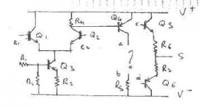
-Do a discrete opamp with class-a output like here:
http://sound.westhost.com/project07.htm
-Driving a buffer with an opamp bias in class A
like ppl do with opa637,el-2002,and mpf-103
(http://www4.head-fi.org/forums/showthread.php?s=&threadid=3254&highlight=cascode+current+source)
or like linear technology do in the data sheet of the LT-1115
Thank you,herve.
I want to increase the bias current of my final stage.
But it is not necessary to have a powerful output.
What can i do?
-Do nothing,it's a stupid idea and let the opamp like it is.
-Do a discrete opamp with class-a output like here:
http://sound.westhost.com/project07.htm
-Driving a buffer with an opamp bias in class A
like ppl do with opa637,el-2002,and mpf-103
(http://www4.head-fi.org/forums/showthread.php?s=&threadid=3254&highlight=cascode+current+source)
or like linear technology do in the data sheet of the LT-1115
Thank you,herve.
herve said:
That discrete amp certainly looks interesting.
But perhaps I'd leave an option on the pcb to add a 68 ohm resistor between Q3's emitter and the V- supply. You can use the resistor or a wire later.
Carlos
herve, what is the whole purpose of this? Signal, load etc?
If you use any good opamp (AD8610, OPA134, OPA627 etc.) plus a buffer like BUF634 you'll get very good results.
If you use any good opamp (AD8610, OPA134, OPA627 etc.) plus a buffer like BUF634 you'll get very good results.
An externally hosted image should be here but it was not working when we last tested it.
If you want to make a discrete opamp, then take a look here:
http://www.passdiy.com/pdf/diyopamp.pdf
http://www.passdiy.com/pdf/diyopamp.pdf
") ) circuit solution.
) circuit solution.
 on all???
Well,an option on the pcb to add a 68 ohm resistor it's maybe a good idea.
But for Q1,Q2 do i need a pair of transistors in the same package like with an LM394?
The purpose of this is not for making an headphone amplifier.
The amplification factor is around 1000.
Maximum output around 1 volt.
Load: 10 to 100 kilo resistor.
The "idea" is to make a final stage with transistors which work "far away" from the cutoff current..
Forgive me for my English.
Regards,herve.
If you want good quality gain of 1000 an opamp in this category will be good and without a buffer. You need a buffer if you need more output current than 10-20 mA. Most opamps can handle 10 volts into 1 kohms loads.
Low noise opamps
LT1037
LT1028
LT1128
LT1115
AD797
OPA627
NE5534 (a litlle bit old but worth the money, I can sell those for 3 SEK a piece)
Not so low noise
OPA134
AD8610
plus many many more
Did I mention that I have LT1028 for sale?
1 USD = 7 SEK (including exchange)
1 EUR = 8 SEK (including exchange)
Buffers
You might try something like this.
http://www.digido.com/User/Assets/Active/PDF files/00478-buffer.pdf
I think this will easily satisfy line drive requirements and drive a headphone amp.
One of the advantages of a topology like this is that the the op amp "see's" a predominantly resistive load. The output buffer deals with the real load. This allows you to use "lightweight" drive op amps and turn them into a killer line driver.
herve said:Well,an option on the pcb to add a 68 ohm resistor it's maybe a good idea.
But for Q1,Q2 do i need a pair of transistors in the same package like with an LM394?
The purpose of this is not for making an headphone amplifier.
The amplification factor is around 1000.
Maximum output around 1 volt.
Load: 10 to 100 kilo resistor.
The "idea" is to make a final stage with transistors which work "far away" from the cutoff current..
Most discrete line preamps are usually designed to work in class-A, even if that is usually stated when you have to handle high currents or drive difficult loads.
Using a mated pair for the input transistors is certainly a good idea.
That ESP discrete preamp has an option to null offset, as you can see from the article, and you should use it. Perhaps an output capacitor, if your power amp does not have one, is probably a good idea.
Rod also warns that input impedance is not so good, but as long as you do not feed high impedance into it you should be fine. Most sources nowadays are low impedance anyway.
Rod also thinks this preamp is in a lower league than an NE5532, for instance, but whether if it sounds better or not is something to be found out. He is an "objectivist", if such a thing exists, so he mostly refers to data comparison for that statement.
Carlos
Well,it'is not a matter of class(A,AB).
The idee is:if i have a lot of current bias,the swing current will be a very small change in my circuit.
It is or not a good idea?
I have a question to Per-Anders.
I have seen (if i make no mistake),that you use in your phono amplifier a buffer and class a circuit:
http://home.swipnet.se/~w-50719/hifi/qsxm3/schema_qsxm3.html
and this is why i wonder at that kind of solution.
Herve.
PMA said:ACD,
that's just a basic, nothing more (DIYopamp). 34 years ago there was a better example of Sinclair Z-30 or Z-50.
I did not know that Audio precision did exist 34 years ago

Herve, your intuition is correct. However; the alternate circuits presented are not optimum. The all discrete circuit is too crude. The added current source in the second example is too complex for just an IC. However, the second alt will work OK, except that discrete is better.
Well,i have try to make a kind of classification...
(I don' talk about feedback to stay simple).
I can use a good quality opamp like Per Anders suggest me.
The "output voltage" is very low and it seems not necessary to bias the opamp into Class A.
well if i use a buffer ,i can add a switch to bypass it and see what is the best way.
i can use in first time a very simple buffer like jam
( http://www.diyaudio.com/forums/showthread.php?s=&threadid=3395&highlight=best+discrete+opamp+buffer)
and in second time a buf 634 like ppl
http://www.diyaudio.com/forums/showthread.php?s=&threadid=372&highlight=best+discrete+opamp+buffer
well i can do or draw like sonnya a complete discrete solution if i have more time (and/or money) and more knowledge.
http://www.diyaudio.com/forums/showthread.php?s=&threadid=1794&highlight=sonnya
It seems to me that ,Rod Elliott or Nelson Pass discrete opamp have been not draw for an application like me.
Tell me if i have made a mistake.
Thank you.
- Status
- This old topic is closed. If you want to reopen this topic, contact a moderator using the "Report Post" button.
- Home
- Amplifiers
- Solid State
- increase the bias current of an opamp final stage