For jaenker, a sneak preview:
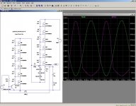
Self-cascoding allows you to build arbitrary blocks of UHV composite transistors.
Here is an example of SRPP having a 4KVpp+ output voltage capability.
The stack can be expanded arbitrarily to suit the needs.
This is the principle only, actual circuit has to include safety systems for balancing, protection, etc.
That's theory. Not something for beginners.
Attachments
I would call that cascade or series connection
cascode fixes the V across one Q - the cascade divides the V change equally
small C in the gate drive divider string are needed for high frequency division accuracy - otherwise the bottom Q can be cut off and see the whole V before the upper Q which are driven thru the divider R
cascode fixes the V across one Q - the cascade divides the V change equally
small C in the gate drive divider string are needed for high frequency division accuracy - otherwise the bottom Q can be cut off and see the whole V before the upper Q which are driven thru the divider R
Yuck, that looks terrible. Tug on the bottom and the top transistors all avalanche in order! At the very least, you need equalizing capacitors along the resistor chain, which is an interesting challenge as Cgs and Cgd vary with voltage. Tall stacks exacerbate the problem, as the bottom transistor (in this example) serves as a common-source amp, while the subsequent stages act like source followers, setting Vds for the previous transistors, except for Cgs, which will tend to yank on the resistors unevenly as the change propagates. When the wave gets to the top, it finally starts pulling itself down, now contracting from the top rather than the bottom. After a very long time, the resistors settle out the charge and things reach equilibrium (~100us?).
Now, the cap divider action means the voltage response won't be as terrible as my hyperbolizing suggests, and the dampening of the resistors will tend to make it behave as an RC transmission line, rather than a wave traveling along an LC section (or worse yet, an LC section *with gain*). It will work fine at "DC" (which is basically audio frequencies) if that's all you're doing, but that's missing the point, DC is dividers and bias resistors, it isn't where the excitement is at.
I'd be very interested to see the square wave response, say replace V1 with a PULSE source, -4V initial, +4V pulsed, 10ns rise/fall time, 50us pulse width, 100us period, along with a plot of the voltage distribution along the stack. If it turns out more uniform than I thought, I might have an extra pair of shoes I can sautee.
Strange, you've got a stack of six 600V devices, if I'm reading it correctly? And a supply of 5000V (of which you're using about 4650V peak in this example)? Do check that LT put in the correct models, those should NOT be handling 775V. For instance, if the models are MODELs only, not SUBCKTs, they will not have representative capacitances, breakdown voltage or reverse capacity. Beware the hazards of trusting someone else's SPICE models!
The last 800V ST FET I played with broke down right on target, something like 870V.
Tim
You probably missed the warning message:Yuck, that looks terrible. Tug on the bottom and the top transistors all avalanche in order! At the very least, you need equalizing capacitors along the resistor chain, which is an interesting challenge as Cgs and Cgd vary with voltage. Tall stacks exacerbate the problem, as the bottom transistor (in this example) serves as a common-source amp, while the subsequent stages act like source followers, setting Vds for the previous transistors, except for Cgs, which will tend to yank on the resistors unevenly as the change propagates. When the wave gets to the top, it finally starts pulling itself down, now contracting from the top rather than the bottom. After a very long time, the resistors settle out the charge and things reach equilibrium (~100us?).
Now, the cap divider action means the voltage response won't be as terrible as my hyperbolizing suggests, and the dampening of the resistors will tend to make it behave as an RC transmission line, rather than a wave traveling along an LC section (or worse yet, an LC section *with gain*). It will work fine at "DC" (which is basically audio frequencies) if that's all you're doing, but that's missing the point, DC is dividers and bias resistors, it isn't where the excitement is at.
I'd be very interested to see the square wave response, say replace V1 with a PULSE source, -4V initial, +4V pulsed, 10ns rise/fall time, 50us pulse width, 100us period, along with a plot of the voltage distribution along the stack. If it turns out more uniform than I thought, I might have an extra pair of shoes I can sautee.
Strange, you've got a stack of six 600V devices, if I'm reading it correctly? And a supply of 5000V (of which you're using about 4650V peak in this example)? Do check that LT put in the correct models, those should NOT be handling 775V. For instance, if the models are MODELs only, not SUBCKTs, they will not have representative capacitances, breakdown voltage or reverse capacity. Beware the hazards of trusting someone else's SPICE models!
The last 800V ST FET I played with broke down right on target, something like 870V.
Tim
This illustrates the principle, with the models available in LTspice's native libraries.This is the principle only, actual circuit has to include safety systems for balancing, protection, etc.
That's theory. Not something for beginners.
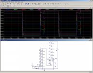
The actual circuit has to include balancing, protection, slew-rate control, etc (and obviously devices having very good safety margins for voltage, current, power and SOA)
In fact, the actual circuits have more protection components than "functional" ones, but the way they are implemented is highly dependent on the application: the situation for a HV ballast is not that of an amplifier.
Anyway, here is the sim you asked for, first completely raw, then with a single 1.5pF capacitor across the 2Meg feedback resistor:
Attachments
I have used this type of configuration successfully although I have not ventured into the kilovolt range yet.
Here is a link were I show my designs,
http://www.diyaudio.com/forums/head...discrete-class-headphone-amp.html#post2596223
The first two I have built ,the third one shows how the added capacitor should be configured for each level and this shows a much better performance in the sims.
The rest of them are some hotrodded versions of some Aleph amp configurations or Class A Push-Pull For driving some ESL panels.
The 50v version was designed for a 1 ohm load and is a monster for a Class A amp,Although I wouldn't suggest using the IRF530's for the output devices,IRF240's or something would be a better choice.
I have used the second circuit in a push-pull design driving a little piezo waffer and it worked really good and sounded very clean for what it was.
I thought the little disk was going to shatter but it didn't.
That was as far as I got and I plan to do some more work like this soon.
I also have several versions using a 1000v IRF BG30's drawn up, as Jameco had a stockpile of these for less than $2 a peice.
I am not sure if they have anymore but they might as last time I checked they did.
I was going to use a couple stacks (4 X 4,16 devices) powered off of a MOT for a DD Esl amp.
This was before I had figured out how to design a CCS as the power resistors required for the thing are quite costly for a 900 watt power dissapation for each leg (X4).
The 1000v version sims with no errors as well as the others.
Great Subject !!!
jer")
Here is a link were I show my designs,
http://www.diyaudio.com/forums/head...discrete-class-headphone-amp.html#post2596223
The first two I have built ,the third one shows how the added capacitor should be configured for each level and this shows a much better performance in the sims.
The rest of them are some hotrodded versions of some Aleph amp configurations or Class A Push-Pull For driving some ESL panels.
The 50v version was designed for a 1 ohm load and is a monster for a Class A amp,Although I wouldn't suggest using the IRF530's for the output devices,IRF240's or something would be a better choice.
I have used the second circuit in a push-pull design driving a little piezo waffer and it worked really good and sounded very clean for what it was.
I thought the little disk was going to shatter but it didn't.
That was as far as I got and I plan to do some more work like this soon.
I also have several versions using a 1000v IRF BG30's drawn up, as Jameco had a stockpile of these for less than $2 a peice.
I am not sure if they have anymore but they might as last time I checked they did.
I was going to use a couple stacks (4 X 4,16 devices) powered off of a MOT for a DD Esl amp.
This was before I had figured out how to design a CCS as the power resistors required for the thing are quite costly for a 900 watt power dissapation for each leg (X4).
The 1000v version sims with no errors as well as the others.
Great Subject !!!
jer
Last edited:
a Leach amp used 2 series devices sucessfully
the Koss E-90 electrostatic headphone amp uses 3x series 450 V TO-92 devcies (and 2x parallel) for each side of a complementary push-pull output running from +/-600 V
I anticipate using 2x IXYS series cascaded 1 kV Mosfets for a project but may just buy the higher V device which came out later - there are now several multi-kV MOSFET and SiC FET devcies that would cut the number required in series
You probably missed the warning message:
This illustrates the principle, with the models available in LTspice's native libraries.
Oops, fair enough..
The actual circuit has to include balancing, protection, slew-rate control, etc (and obviously devices having very good safety margins for voltage, current, power and SOA)
In fact, the actual circuits have more protection components than "functional" ones, but the way they are implemented is highly dependent on the application: the situation for a HV ballast is not that of an amplifier.
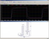
Anyway, here is the sim you asked for, first completely raw, then with a single 1.5pF capacitor across the 2Meg feedback resistor:
Dang, seems a little high on the voltage, like it's close to or in clipping. Waveforms don't look too bad but there might be some interesting transient behavior going on. That bounce on the first waveform was interesting!
Tim
- Status
- This old topic is closed. If you want to reopen this topic, contact a moderator using the "Report Post" button.
- Home
- Amplifiers
- Solid State
- Self-cascoding, a tool for creating ultra high voltage building blocks: