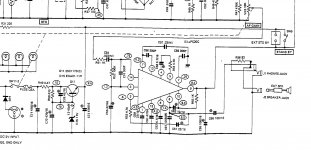
Hi. I recently acquired a Realistic DX-160 Communications Receiver, made around 1975. The audio circuit does not work -- the chip is bad. I am going to order a new replacement chip. My question is concerning what I think are bandpass filters surrounding the chip. Can anybody help me determine the nature of these and why they are there? See the image of part of the schematic containing the audio circuit. If needed I can provide a datasheet of the chip. The schematic contains the values of the parts.
Attachments
OK I'll take a shot. There seems to be more than nessisary parts around that chip. Because this is a communications reveiver perhaps they are doing some audio emphasis -demphasis depending on the type of station. They may even switching the tone automatically. I would be intrested in seeing the datasheet.
A communications receiver might well have some sort of filtering to make the most of poor signals. The datasheet would be of help in figuring it out. Google draws a blank on it, BTW.
Are those uPC20C chips still available? Better grab one while you can.")
No, the uPC20C is obsolete. Mouser has a replacement -- the NTE1075A. I will attach the datasheet for that one.
Attachments
Hi,
HAM radios AFAIK are designed to maximise speech intelligibility with very
poor signals with loads of interference. Often the interference is in ranges
you don't need for intelligibility but much higher in level than what you wan't.
It gets in the way, so chuck it away and only use the ranges you need.
Not the sort of radio you'd want to listen to music on, basically, but it allows
signals to be understood you would not be able to understand unfiltered.
Some I understand have some very clever DSP adaptive filtering.
rgds, sreten.
Last edited:
I've listened to a few DX160s over the years before synthesised tuners were adopted. I wouldn't say the audio was particularly filtered as in a serious comms. receiver, as they made a fair AM receiver too. It is usual in budget receivers to carry out bandpass filtering primarily by the IF bandwidth. Post or audio filtering for various impulse or wideband noise, is by intermediate adjustable/switchable filters.
Unlike modern, one chip audio amps, most early ones needed a bucketload of external caps to make them even function. The likelihood of RF leaked into the audio and mussing up the amp's operation might be a good reason for placing filters there.
Unlike modern, one chip audio amps, most early ones needed a bucketload of external caps to make them even function. The likelihood of RF leaked into the audio and mussing up the amp's operation might be a good reason for placing filters there.
While trawling the interweb, I found the following bit of info that might be of some use.
An externally hosted image should be here but it was not working when we last tested it.
[FONT=verdana, arial, sans serif, helvetica]Howard provided some information on improving the audio response of the DX-160. Here are his recommendations:
Howard says that while he doesn't get the bass response he does from a DX-302, he was able to get rid of the nasal sound and adds a lot of punch that it didn't have before. Thanks Howard!
- C54 - 22 mfd 50V (If any instability is observed such as excessive time before hearing any sound when powering up, change this capacitor to 10mfd 50V)
- C56 - 220mfd 16V
- C58 - 10 mfd 35V or greater
- C63 - 1000 mfd 16V or greater
- C64 - Remove this capacitor as this will limit top end response
[/FONT]
W4JBM's Realistic DX-160 Page
For one thing, the output coupling cap (C66) certainly is on the meagre side for speaker operation. That one should be like 470..1000µ then. C63 seems to be a bootstrap cap, enlarging this by about the same factor seems worth a shot. For everything else, the NTE datasheet is not detailed enough.
In general, I wouldn't trust average quality mid-1970s electrolytics too much any more. If the unit should still be using carbon comp resistors, these should be checked for upwards drift, too.
In general, I wouldn't trust average quality mid-1970s electrolytics too much any more. If the unit should still be using carbon comp resistors, these should be checked for upwards drift, too.
For one thing, the output coupling cap (C66) certainly is on the meagre side for speaker operation. That one should be like 470..1000µ then. C63 seems to be a bootstrap cap, enlarging this by about the same factor seems worth a shot. For everything else, the NTE datasheet is not detailed enough.
In general, I wouldn't trust average quality mid-1970s electrolytics too much any more. If the unit should still be using carbon comp resistors, these should be checked for upwards drift, too.
Thank you for that valuable information. I'm going to replace the resistors with 1% tolerant metal film. My decision to repair the circuit rather than build a new, separate one is so the unit is kept in relatively original condition. Later on I might build a custom external amp and have it so I can change back and forth. That way it retains it's nostalgia factor.
Unfortunately this is a pretty pedestrian receiver... ie. not that good.
The audio chip ur looking at is nothing special as far as I can tell... what the freq response of the circuit is can be guessed at looking at the thing... the datasheet would tell the story. Regardless, it hardly matters what you throw into that spot, although finding one would make things easier. ARE YOU SURE the chip is bad??
I see you have a Lafayette receiver below... tubes?
The 1%MF resistors are overkill, and probably not worth the effort unless you find a bad resistor in there. Change the electrolytics, or check them for leakage by noticing unusual offsets, etc... the voltage are shown in the schematic.
Quite frankly, I'd shop for a better receiver if you want performance. Unless ur into doing projects because you enjoy them, I think ur time would be better spent on another receiver.
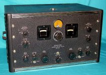
Consider a Hammarlund SP-200 or the equivalent HX-whatever? They are neat old boatanchors, frequently found in "as-is" condition and missing the separate PS (easy to duplicate) and are worthy of a restoration project's time and elbow grease because when you are done you have a classic that actually works well too...
Just my 2 cents worth... ymmv.
_-_-bear
The audio chip ur looking at is nothing special as far as I can tell... what the freq response of the circuit is can be guessed at looking at the thing... the datasheet would tell the story. Regardless, it hardly matters what you throw into that spot, although finding one would make things easier. ARE YOU SURE the chip is bad??
I see you have a Lafayette receiver below... tubes?
The 1%MF resistors are overkill, and probably not worth the effort unless you find a bad resistor in there. Change the electrolytics, or check them for leakage by noticing unusual offsets, etc... the voltage are shown in the schematic.
Quite frankly, I'd shop for a better receiver if you want performance. Unless ur into doing projects because you enjoy them, I think ur time would be better spent on another receiver.
Consider a Hammarlund SP-200 or the equivalent HX-whatever? They are neat old boatanchors, frequently found in "as-is" condition and missing the separate PS (easy to duplicate) and are worthy of a restoration project's time and elbow grease because when you are done you have a classic that actually works well too...
Just my 2 cents worth... ymmv.
_-_-bear
Last edited:
Here is more information on these receivers than you can shake a stick at, it gets more interesting
to the middle and end of this very long webpage...
http://www.radioblvd.com/hammarlund_super_pro.htm
What it looks like:
to the middle and end of this very long webpage...
http://www.radioblvd.com/hammarlund_super_pro.htm
What it looks like:
Attachments
Last edited:
@ bear: Thanks for the useful information. I'll have a read of the link you posted on the Hammarlund. Yes, I'm 100% positive the chip is bad. The Lafayette receiver is not mine. I think it belongs to the person who wrote the page ingenieus was talking about. I believe ingenieus got that image from said page. I'm still going to fix the Realistic receiver, I do enjoy projects like that even though it's not the best it's worth the time and effort to me.
- Status
- This old topic is closed. If you want to reopen this topic, contact a moderator using the "Report Post" button.
- Home
- Amplifiers
- Solid State
- Bandpass filters in audio circuit of communications receiver?