CE + CC
This circuit will have very bad biasing stability, big voltage drift. Current flow by this parallel connected transistors will depend on curve of beta both transistors, distortion - no glory. If you can do every five minutes " living DC servo " with your screwdriver, go on. I mean, that after one day your enthusiasm will not so strong and you get it into ashcan. Search your inspiration on pages of fa Bryston, for example on circuit diagram of amplifier 4 Bst.
This circuit will have very bad biasing stability, big voltage drift. Current flow by this parallel connected transistors will depend on curve of beta both transistors, distortion - no glory. If you can do every five minutes " living DC servo " with your screwdriver, go on. I mean, that after one day your enthusiasm will not so strong and you get it into ashcan. Search your inspiration on pages of fa Bryston, for example on circuit diagram of amplifier 4 Bst.
PMA said:
Howdy, Pavel.
Sure have.
Several years ago I got the notion of building a relatively low power amplifier using a step-up transformer in order to achieve the voltage gain purely passively and using active devices only as followers for impedance transformation.
Since then as the mood strikes, I've been trying different follower configurations. I've tried MOSFETs but for me anyway, I haven't liked them as much as bipolars and JFETs.
Have you tried using a JFET for your follower?
So far I've gone through pretty much every iteration of followers using solid state devices. About the only thing I've left to try is an all JFET follower.
se
Can't find much on a google search... do you have a link to this?Search your inspiration on pages of fa Bryston, for example on circuit diagram of amplifier 4 Bst.
Do you think it's this effect will be worse than in a quasi-complimentary setup?Current flow by this parallel connected transistors will depend on curve of beta both transistors, distortion - no glory.
Assuming the topology is to remain unchanged, what do you suggest as a solution to the biasing instability you describe? I realize no provision has (yet) been made for thermal compensation. By what other means do you foresee such drift to occur?This circuit will have very bad biasing stability, big voltage drift.
Steve:
>Didn't make much sense when I hitched an N-channel silicon JFET to a PNP germanium bipolar. But it sounded fantastic.<
Cool! I'm doing something similar in a line-level output follower. In a nutshell, it marries a JFET N to a bipolar PNP (both silicon). The standing current is fairly high , so each device is additionally cascoded with a bootstrapped MOSFET. The circuit looks a tad complex and funky, but has been very reliable and production-friendly (it is self-calibrating), and measures quite well. The only significant downside is that, due to the bootstrapped cascodes, the voltage utilization isn't terribly efficient.
The sound?
>I've gone through pretty much every iteration of followers using solid state devices.<
*Every* iteration? Interesting... Approximately how many follower configurations have you gone through?
jonathan carr
>Didn't make much sense when I hitched an N-channel silicon JFET to a PNP germanium bipolar. But it sounded fantastic.<
Cool! I'm doing something similar in a line-level output follower. In a nutshell, it marries a JFET N to a bipolar PNP (both silicon). The standing current is fairly high
, so each device is additionally cascoded with a bootstrapped MOSFET. The circuit looks a tad complex and funky, but has been very reliable and production-friendly (it is self-calibrating), and measures quite well. The only significant downside is that, due to the bootstrapped cascodes, the voltage utilization isn't terribly efficient.The sound?
>I've gone through pretty much every iteration of followers using solid state devices.<
*Every* iteration? Interesting...
Approximately how many follower configurations have you gone through?jonathan carr
Can't find much on a google search... do you have a link to this?
http://www.bryston.ca/schemprod.html
jcarr said:Cool! I'm doing something similar in a line-level output follower. In a nutshell, it marries a JFET N to a bipolar PNP (both silicon). The standing current is fairly high
The sound?
Nice!
With the simplest CFP circuit I've only been able to keep the germanium behaved at line levels into typical loads. They sound fantastic but they're REALLY twitchy when it comes to thermal stability and they'll start running away faster than you can say "What's that funny smell?"
I'd planned on scaling it up to handle a couple amps in order to drive a loudspeaker load but I'm debating whether the added circuitry to keep it reasonably stable thermally will be worth it.
I got the notion to try germaniums from when my DIY activities centered around doing stuff music (electric guitar). Back in the 80s I'd experimented with the original Fuzz Face circuit and when I'd tried it with silicon transistors instead of the germaniums used in the original, it didn't sound nearly as good.
Even though the Fuzz Face is intended to generate gobs of distortion, I wondered how germaniums would do in this simple follower application.
I was quite surprised.
*Every* iteration? Interesting...
Well, pretty much every BASIC iteration. Not using cascoding or things like that. But I've gone through just about every iteration of single and compound (both Darlington and Sziklai) followers with both active and passive loads. I guess if you count using different device types in the same topology, we're talking around a dozen.
The best to me so far, but only at line levels at this point has been the JFET/germanium CFP.
Right now I'm starting on an all JFET version using JFETs in a "single" follower with the JFETs paralleled. Been wanting to do a headphone amplifier so I'm going to give that a go with half a dozen or so JFETs in parallel and if that works out, I'll gradually scale it up and see if I can eventually get half a dozen watts or so into 8 ohms.
se
Steve:
>With the simplest CFP circuit I've only been able to keep the germanium behaved at line levels into typical loads. They sound fantastic but they're REALLY twitchy when it comes to thermal stability<
I haven't studied germaniums, so I don't know how they would behave. Besides, the circuit that I am using is anything _but_ simple, and that self-calibration mechanism appears to do a pretty good job at quenching any tendancies towards thermal runaway (at least I have yet to observe anything so far).
>I'd planned on scaling it up to handle a couple amps in order to drive a loudspeaker load but I'm debating whether the added circuitry to keep it reasonably stable thermally will be worth it.<
I've adopted the aforementioned circuit for BJTs and enhancement MOSFETS (the range of available depletion MOSFETs being excruciatingly confining, while SITs are next to impossible to get) and tried it in a power amp, but the self-calibrating mechanism turned out to be a liability in this particular situation. The self-calibrator acts as a regulator for the standing current, which is fine for gentle loads where not much power is being dissipated, but becomes a bottleneck for difficult loads when you _want_ to pump a lot of power. No matter what you do, no matter what the load, the circuit wants to operate at a fixed amount of current. If you want the thing to drive a 2-ohm load, you need to set up the circuit that it is _always_ passing enough current for a 2-ohm load. "Hmmm, kinda warm in here, in' it?"
>Well, pretty much every BASIC iteration. Not using cascoding or things like that.<
Ah. I use singles, compounds, load-dependent compounds, bootstrapped cascoding, current-sensing, load-sensing, multiple and nested feedback loops, NFB, PFB ... Pretty much anything that looks like it could improve the performance (or even just be fun to try) gets thrown in the blender, making the number of possible circuit permutations mind-boggling. Incidentally, the particular line-level follower that I have been talking about contains about 20 components by itself.
>The best to me so far, but only at line levels at this point has been the JFET/germanium CFP.<
There are some dual-gate and GaAs FETs that I've used in video circuits that may be fun to use in audio circuits, but so far, I cannot count germanium among my engineering ingredients. Perhaps I will try it out some time.
>I'm starting on an all JFET version using JFETs in a "single" follower with the JFETs paralleled. Been wanting to do a headphone amplifier so I'm going to give that a go with half a dozen or so JFETs in parallel.<
If you use SOT-23s, I'm sure that you could fit a lot more JFETs into an equivalent board space .
.
regards, jonathan carr
>With the simplest CFP circuit I've only been able to keep the germanium behaved at line levels into typical loads. They sound fantastic but they're REALLY twitchy when it comes to thermal stability<
I haven't studied germaniums, so I don't know how they would behave. Besides, the circuit that I am using is anything _but_ simple, and that self-calibration mechanism appears to do a pretty good job at quenching any tendancies towards thermal runaway (at least I have yet to observe anything so far).
>I'd planned on scaling it up to handle a couple amps in order to drive a loudspeaker load but I'm debating whether the added circuitry to keep it reasonably stable thermally will be worth it.<
I've adopted the aforementioned circuit for BJTs and enhancement MOSFETS (the range of available depletion MOSFETs being excruciatingly confining, while SITs are next to impossible to get) and tried it in a power amp, but the self-calibrating mechanism turned out to be a liability in this particular situation. The self-calibrator acts as a regulator for the standing current, which is fine for gentle loads where not much power is being dissipated, but becomes a bottleneck for difficult loads when you _want_ to pump a lot of power. No matter what you do, no matter what the load, the circuit wants to operate at a fixed amount of current. If you want the thing to drive a 2-ohm load, you need to set up the circuit that it is _always_ passing enough current for a 2-ohm load. "Hmmm, kinda warm in here, in' it?"
>Well, pretty much every BASIC iteration. Not using cascoding or things like that.<
Ah. I use singles, compounds, load-dependent compounds, bootstrapped cascoding, current-sensing, load-sensing, multiple and nested feedback loops, NFB, PFB ... Pretty much anything that looks like it could improve the performance (or even just be fun to try) gets thrown in the blender, making the number of possible circuit permutations mind-boggling. Incidentally, the particular line-level follower that I have been talking about contains about 20 components by itself.
>The best to me so far, but only at line levels at this point has been the JFET/germanium CFP.<
There are some dual-gate and GaAs FETs that I've used in video circuits that may be fun to use in audio circuits, but so far, I cannot count germanium among my engineering ingredients. Perhaps I will try it out some time.
>I'm starting on an all JFET version using JFETs in a "single" follower with the JFETs paralleled. Been wanting to do a headphone amplifier so I'm going to give that a go with half a dozen or so JFETs in parallel.<
If you use SOT-23s, I'm sure that you could fit a lot more JFETs into an equivalent board space
.regards, jonathan carr
jcarr said:I haven't studied germaniums, so I don't know how they would behave. Besides, the circuit that I am using is anything _but_ simple, and that self-calibration mechanism appears to do a pretty good job at quenching any tendancies towards thermal runaway (at least I have yet to observe anything so far).
Me either. I just dove right in. Fortunately I was constantly monitoring the current so I was able to shut down before anything got too out of hand. The germaniums I was using for this (NTE104s) cost me $13 a pop so I use a bit of extra precaution.
I've adopted the aforementioned circuit for BJTs and enhancement MOSFETS (the range of available depletion MOSFETs being excruciatingly confining, while SITs are next to impossible to get) and tried it in a power amp, but the self-calibrating mechanism turned out to be a liability in this particular situation. The self-calibrator acts as a regulator for the standing current, which is fine for gentle loads where not much power is being dissipated, but becomes a bottleneck for difficult loads when you _want_ to pump a lot of power. No matter what you do, no matter what the load, the circuit wants to operate at a fixed amount of current. If you want the thing to drive a 2-ohm load, you need to set up the circuit that it is _always_ passing enough current for a 2-ohm load. "Hmmm, kinda warm in here, in' it?"
Yeah, that's why I'm debating whether to take any drastic measures for thermal stability here. I'm afraid it might end up spoiling things too.
Not worrying about things such as 2 ohm loads though. I'm only shooting for about 6 watts into 8 to drive high efficiency speakers which unless there's some really wacky crossover in 'em, are generally 8 ohms nominal or higher.
Ah. I use singles, compounds, load-dependent compounds, bootstrapped cascoding, current-sensing, load-sensing, multiple and nested feedback loops, NFB, PFB ... Pretty much anything that looks like it could improve the performance (or even just be fun to try) gets thrown in the blender, making the number of possible circuit permutations mind-boggling. Incidentally, the particular line-level follower that I have been talking about contains about 20 components by itself.
20? Yikes!
I'm still intrigued by what can be done with the simplest circuits. I'd tried some really simpl common emitter/source circuits but didn't care much for 'em. That's when I decided to try splitting the workload using a transformer for voltage gain and using the active devices as followers where I've found much better results with really simple topologies.
There are some dual-gate and GaAs FETs that I've used in video circuits that may be fun to use in audio circuits, but so far, I cannot count germanium among my engineering ingredients. Perhaps I will try it out some time.
Well, depending which route I decide to take, I've got a pair of NTE104s you can have.
If you use SOT-23s, I'm sure that you could fit a lot more JFETs into an equivalent board space
Hehehe. True. Hmmm... Wonder how hard it'd be to point-to-point wire SOT-23s... That'd certainly give a lot more airflow.
se
I'll be damned...
Thanks for the link guys... I'll be damned! Bryston have got a very similar setup. The major difference as I see it is that the dual CC/CE stages share OR22 resistors in my setup, causing local NFB.
I guess it's true: there really is nothing new under the sun...
Attached the Bryson o/p stage for fun:
Attachments
Dr. G:
>I guess it's true: there really is nothing new under the sun...<
Not necessarily. Sometimes you design something which has already been invented elsewhere (most recent example in my case would be the "Baxandall" pair), but sometimes you design something that works well, but years later, you still never find mentioned anywhere outside of your own circuits. You just have to keep thinking, trying and working.
Besides, don't automatically take it as a bad sign if it turns out that something that you develop has been previously invented by someone else. To put a positive spin on it, you may choose to consider it as verification that the design issues that you are thinking of may actually mean something for the performance. Such verification may imply that you are _not_ off on some wild goose chase...
Keep on trying!
regards, jonathan carr
jcarr said:Not necessarily. Sometimes you design something which has already been invented elsewhere (most recent example in my case would be the "Baxandall" pair), but sometimes you design something that works well, but years later, you still never find mentioned anywhere outside of your own circuits. You just have to keep thinking, trying and working.
Besides, don't automatically take it as a bad sign if it turns out that something that you develop has been previously invented by someone else. To put a positive spin on it, you may choose to consider it as verification that the design issues that you are thinking of may actually mean something for the performance. Such verification may imply that you are _not_ off on some wild goose chase...
An externally hosted image should be here but it was not working when we last tested it.
se
I hear that train a coming......
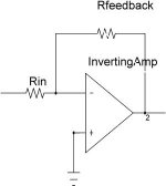
"Inherent in inverting stages. Not a trainsmash."
Inverting amplifiers have a ground reference, the noninverting input.
Where in the circuit is that exactly........
Any of you guys ever heard of vaporware?
http://www.footballsoftware.com/
Maybe we can have a fantasy amplifier thread. No simulation, specs, measurements, or schematics with part values. a simplefied schematic or vauge desription will be fine.
Attachments
Right now just thinking and chilling... the concept is hybrid. I feel comfortable with the tube VAS/driver section. I'm basically considering "different/new" arrangements for a low/unity gain silicon o/p stage, preferably inverting. And this was just an idea. If you have others I'd be keen to listen.DrG, what is your goal? What do you want to achieve?
Fred Dieckmann:
Well I'll be damned...Inverting amplifiers have a ground reference, the noninverting input.
Can't find it, sorry. Why don't you have another look. Or take a squizz at Nelson Pass' Zen 5, on which part of my circuit is based... it seems to be "missing" the same graound reference heheheheWhere in the circuit is that exactly...
Ok... can we call it the Dieck-thread do you think?Maybe we can have a fantasy amplifier thread. No simulation, specs, measurements, or schematics with part values. a simplefied schematic or vauge desription will be fine.
- Status
- This old topic is closed. If you want to reopen this topic, contact a moderator using the "Report Post" button.
- Home
- Amplifiers
- Solid State
- Opinions on this amp...?