Sakis,
Few minutes ago while listening to great Billy Eckstine performance of "Jelly, Jelly" from 1972 Newport in New York concert (with great solos from Sonny Stitt and Dizzy Gillespie) it suddenly appeared to me that you mentioned somewhere (but I can not remember where) that old amps had tone control circuit inside feedback loop of power amp section.
Well, that is very important fact for the subjective impression of sound quality. My friend used tone controls on his old Technics for decades, and the sound was very good indeed. But when he replaced it with new Marantz that has op-amp based tone controls in preamp section, the sound of tone controls was very bad. So bad, in fact, that after 30 years of using tone controls he stopped using them. It is my impression that placing tone control circuit inside feedback loop of P3A could be an interesting experiment. No matter how incorrect it is in purely technical sense, I think that no solution is bad until proven bad by subjective tests.
Again, I think that Japanese engineers tried it in prototypes, and found that it is place where it belongs, in the power amp section. After all, they depend on how products will be accepted by consumers, so for them, at least in those times, subjective impression was of paramount importance.
Power transistors...
Hi again!,
I noticed that I already have two pairs of MJ15024 and MJ15025 power transistors.
I compared the maximum ratings given in datasheets (with MJL21193/4), and they are equal
Also compared the prices at my local distributor and MJLs are three times more expensive
So I'm considering building the amp with the transistors I have...
Do you think this replacement/mod will considerably affect the sound?
Maybe it's worth mentioning that I'm gonna use it for the woofers in a by-amped system with the crossover cut-off freq. at 330Hz
Link of power device's datasheets:
http://pdf1.alldatasheet.com/datasheet-pdf/view/4875/MOTOROLA/MJL21193.html
http://pdf1.alldatasheet.com/datasheet-pdf/view/4876/MOTOROLA/MJL21194.html
http://pdf1.alldatasheet.com/datasheet-pdf/view/2670/MOSPEC/MJ15025.html
http://pdf1.alldatasheet.com/datasheet-pdf/view/2669/MOSPEC/MJ15024.html
Last edited:
Sakis,
Few minutes ago while listening to great Billy Eckstine performance of "Jelly, Jelly" from 1972 Newport in New York concert (with great solos from Sonny Stitt and Dizzy Gillespie) it suddenly appeared to me that you mentioned somewhere (but I can not remember where) that old amps had tone control circuit inside feedback loop of power amp section.
Well, that is very important fact for the subjective impression of sound quality. My friend used tone controls on his old Technics for decades, and the sound was very good indeed. But when he replaced it with new Marantz that has op-amp based tone controls in preamp section, the sound of tone controls was very bad. So bad, in fact, that after 30 years of using tone controls he stopped using them. It is my impression that placing tone control circuit inside feedback loop of P3A could be an interesting experiment. No matter how incorrect it is in purely technical sense, I think that no solution is bad until proven bad by subjective tests.
Again, I think that Japanese engineers tried it in prototypes, and found that it is place where it belongs, in the power amp section. After all, they depend on how products will be accepted by consumers, so for them, at least in those times, subjective impression was of paramount importance.
Very correct so far indeed some of the first amplifiers of the Japanese included passive tone controls nested in the feedback chain from the output of the amplifier .
the specific application is not really sharp and not exactly very linear in cut 'n boost numbers and also involves more the danger that the load ( speaker +cables ) will modulate the amplifier often in a dangerous way ( increased with long cables and capacitive loads )
Indeed though the specific tone control originally produced very nice colors and unbeatable sonics . Probably if made with quality material and if freq is better targeted will perform even better .
Still form statistics aspect i have absolutely no knowledge and never come to my attention the specific circuit implemented in an sziklai amplifier .
Yes this idea is within my wish list It is something i always wanted to try
Kind regards
Sakis
The specifications aren't quite the same for the older MJ15024/5. The emphasis there is for high Vceo for reliable multiple use in high power pro. amps whilst the MJ or MJL series 21193-6 is for more sustained beta. In meaningful terms, that translates to better linearity as the power increases and is one reason why there is a premium on price. Usually, they do actually sound better than MJ15024 series, when used in small numbers such as 1 or 2 pairs.......So I'm considering building the amp with the transistors I have...
Do you think this replacement/mod will considerably affect the sound?......
The specifications aren't quite the same for the older MJ15024/5. The emphasis there is for high Vceo for reliable multiple use in high power pro. amps whilst the MJ or MJL series 21193-6 is for more sustained beta. In meaningful terms, that translates to better linearity as the power increases and is one reason why there is a premium on price. Usually, they do actually sound better than MJ15024 series, when used in small numbers such as 1 or 2 pairs.
Thank you very much Ian. Now I know it's worth buying them.
Regards,
It is my impression that placing tone control circuit inside feedback loop of P3A could be an interesting experiment.
Harman Kardon HK610 uses tone controls designed into the power amp. section. Service manual here:
Harman/Kardon HK610 Service Manual free download,schematics,datasheets,eeprom bins,pcb,repair info for test equipment and electronics
Harman Kardon HK610 uses tone controls designed into the power amp. section. Service manual here:
Harman/Kardon HK610 Service Manual free download,schematics,datasheets,eeprom bins,pcb,repair info for test equipment and electronics
Michael, thanks for the link. BTW, SOA paper downloaded! Useful read for pros and (us) amateurs alike.
D
Deleted member 148505
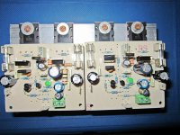
OK, then improve the thermal coupling between drivers and bias transistor so it doesn't take ages to stabilize and responds usefully to changes in dissipation...... im improving it
According to the pics, you don't have a driver heatsink anyway, so what bias current are using now? You don't need to move much to allow better coupling with just a single heatsink for all 3 transistors, assuming you don't already have this arrangement but just haven't shown it here.
D
Deleted member 148505
Hi, the drivers will be connected on a single heatsink. Bias transistor and Q5 are thermally coupled (glued by thermal epoxy), thus changes in Driver transistor Q5 will be quickly monitored by Q9.
5W output collector resistors are on the underside of the PCB.
5W output collector resistors are on the underside of the PCB.
Attachments
Last edited by a moderator:
Member
Joined 2009
Paid Member
D
Deleted member 148505
Hi Tony, where is the oldtimers
I must give it a try...
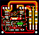
So many critics to my own layout, thanks guys...
time to improving it
I must give it a try...
The Power Ground does not need to be connected to the Signal Ground by using PCB traces.
The Power Ground and the Signal Ground need to be referenced to the same voltage. This can be on board, or it can be off board.
If you are building more than one channel into your amplifier, then I assert that the Main Audio Ground (where Signal ground and Power Ground meet) must be off board.
John Bali
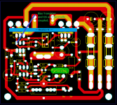
The big filter capacitors have to be located close to the power transistors in order to reduce the inductance added by the long track.
Gajanan Phadte
Nice layout - I also used this approach for my TGM1, TGM2 and TGM3 - having power rails on one side and sensitive parts on other side.
So many critics to my own layout, thanks guys...
time to improving it
Originally Posted by AndrewT
The Power Ground does not need to be connected to the Signal Ground by using PCB traces.
The Power Ground and the Signal Ground need to be referenced to the same voltage. This can be on board, or it can be off board.
If you are building more than one channel into your amplifier, then I assert that the Main Audio Ground (where Signal ground and Power Ground meet) must be off board.
so many words....what does it amount to?
why can't AndrewT just show us in pictures what he's got so we can appreciate what he says....
- Home
- Amplifiers
- Solid State
- Rod Elliot P3A Layout - Critics