.....The attachment shows more suggestions.....")
Sir alex what pcb layout software are you using?
D
Deleted member 148505
Hi alex,
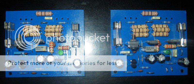
Here's my layout based on your design,. thanks
Here's my layout based on your design,. thanks
An externally hosted image should be here but it was not working when we last tested it.
Hi,Hi alex,
Here's my layout based on your design,. thanks
An externally hosted image should be here but it was not working when we last tested it.
Were did buy those MJL4302,4281? Are they locally available in Raon Phils?
Regards,
D
Deleted member 148505
Hi,
Were did buy those MJL4302,4281? Are they locally available in Raon Phils?
Regards,
I ordered them from OnSemi.
there is not much to say .... there is a million comments regarding pcb designs only you have to read them .
----Attaching the vas to one of the drivers will not provide thermal compensation... attaching the VBE multiplier to one of the drivers may provide some thermal compensation
( to my taste common heatsink both of the drivers and attach VBE on it for the best results )
---Bypass and decoupling will only work for the best if close to the outputs
---especially the one bypass located next to the vas miller cap is a tricky thing to do i t might cause some complication
---It is also wrong to have the LTP in Houston while the current source for it is in NY .... these three will need to be as close is possible
---The zobel and the ground return is or could be dirty so having it going all around the amplifier is not the best thing to do ... obviously one may benefit by re-placing the zobel in the output on the binding post rather than on the pcb...
now ... in real life the pcb you produced ( in a harry ) will work and play music class AB amplifiers are so forgiving ! Point is that if you aim for high quality and low distortion you will never make it with this pcb ....
Does it sound like someone is trying to milk the mosquito ? may be ... but design a pcb under those rules and the particular amp will meet the above specs
D
Deleted member 148505
there is not much to say .... there is a million comments regarding pcb designs only you have to read them .
----Attaching the vas to one of the drivers will not provide thermal compensation... attaching the VBE multiplier to one of the drivers may provide some thermal compensation
( to my taste common heatsink both of the drivers and attach VBE on it for the best results )
---Bypass and decoupling will only work for the best if close to the outputs
---especially the one bypass located next to the vas miller cap is a tricky thing to do i t might cause some complication
---It is also wrong to have the LTP in Houston while the current source for it is in NY .... these three will need to be as close is possible
---The zobel and the ground return is or could be dirty so having it going all around the amplifier is not the best thing to do ... obviously one may benefit by re-placing the zobel in the output on the binding post rather than on the pcb...
now ... in real life the pcb you produced ( in a harry ) will work and play music class AB amplifiers are so forgiving ! Point is that if you aim for high quality and low distortion you will never make it with this pcb ....
Does it sound like someone is trying to milk the mosquito ? may be ... but design a pcb under those rules and the particular amp will meet the above specs
I only attached the two temporarily so that when I solder it, it will be aligned, my goal is to common sink all of them...
Thanks, I'll revise/make another layout based on your suggestions here and on your p3a comparison thread
Last edited by a moderator:
ian .....we ve been through this before .... The work i make for the P3a is based on rods schematic ( minus plus a few things ) but the boards i make i s only for personal use and i am not willing to give to any
Giving or selling boards ( even posting layouts of ) will be against Rod's interest and we all agree to respect a person that given so much in the diy community for free..
At least this is the way i see it
Kind regrads
sakis
Giving or selling boards ( even posting layouts of ) will be against Rod's interest and we all agree to respect a person that given so much in the diy community for free..
At least this is the way i see it
Kind regrads
sakis
But in all honesty, is rod's own layout actually any better than the one posted in this thread ?
He does claim theres no possible way to come anywhere near the performance his boards offers, which is quite frankly pure bs and merely a claim to boost sales of his own boards.
My first ever discrete amp was the P3A and i built it on a piece of plywood with nails hammered into it at the joints on the schematic, worked just fine.
D
Deleted member 148505
Hi sakis I have a noob question,
How close are they should be? Is it relative to the size of the board (lesser interaction to other components) or absolute as in per inch? Because this board is only 3 x 2.5" and if measured in the length of the track I think they are pretty close...these three will need to be as close is possible
Last edited by a moderator:
Put it this way, Tekko - Rod sees a lot of copies of his boards because people think an auto- router in their PC software can do just as good and looks pretty, nice and close together etc. I've made PCBs by hand, artwork and cheap or free software for a lot of years but I can assure you that in hi-end audio and RF work, nothing is as good as someone who knows best spacings and position of parts, track alignments, thermal gradients, EMR patterns and who is designing for A1 performance with the skill and experience for it.
Typically, you can halve THD by smart trackwork in the output transistor traces and feedback routing. You can reduce noise by parts selection and location. Yes, you can learn that there are do's and dont's rules to follow like star grounding paths but do we know how much is necessary for optimum performance of the design? After 10-20 iterations and feedback, you might be getting somewhere. Rod has that experience with his very old designs but I don't think many people see it. It can make that difference between 500 Euro and 5,000 Euro amplifiers and of course, the odds you will ever get paid for any design. There are guys here who are breathtakingly good at commercial work but you see something else when you look inside the best fancy brands.
Sakis - I am just kidding you, see... It is actually a compliment to invite someone, just kidding, to give you what you like, no? Of course they just grin and say something nasty but that's life, we are old enough to understand we can't have everything. I wouldn't seriously ask anyone on Forum for any IP unless they offer it as a group buy etc. Sorry if I offended you, my friend.
Typically, you can halve THD by smart trackwork in the output transistor traces and feedback routing. You can reduce noise by parts selection and location. Yes, you can learn that there are do's and dont's rules to follow like star grounding paths but do we know how much is necessary for optimum performance of the design? After 10-20 iterations and feedback, you might be getting somewhere. Rod has that experience with his very old designs but I don't think many people see it. It can make that difference between 500 Euro and 5,000 Euro amplifiers and of course, the odds you will ever get paid for any design. There are guys here who are breathtakingly good at commercial work but you see something else when you look inside the best fancy brands.
Sakis - I am just kidding you, see...
It is actually a compliment to invite someone, just kidding, to give you what you like, no? Of course they just grin and say something nasty but that's life, we are old enough to understand we can't have everything. I wouldn't seriously ask anyone on Forum for any IP unless they offer it as a group buy etc. Sorry if I offended you, my friend.
D
Deleted member 148505
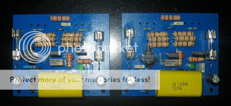
Anyway I already assembled the amp and the only modification that I can make is to have the zobel in the output terminal, too bad I don't have the test equipments to measure and compare it to published specs.
When I powered it up, the amp runs relatively cool with 75mA bias, I will connect it to my main speakers once I integrate a speaker protection circuit...
When I powered it up, the amp runs relatively cool with 75mA bias, I will connect it to my main speakers once I integrate a speaker protection circuit...
Last edited by a moderator:
no worries Ian .... the code of communication between us is very well established so we both speak the same language .....
given the chance to talk about it ..... if you willing to design a pcb for a simple device like the P3a and follow all the mentioned rules above, and some others not mentioned in this thread is actually impossible ( trust me on this one been trying for 5 years in my spare time )
you may as well go for a double layer but then you are swimming in unknown waters like proximity where induction or capacitance between traces and layers will be impossible to evaluate properly for people that don't have experience and/or highly sophisticated equipment .
Conclusion is that you have to "keep" the rules but up to a certain point divided by symmetry /looks and all of it underlined with the cost factor ...
conclusion also is that people that exist in the diy often are bad in mathematics ( like me ) so the above equation is almost impossible to solve ....
happy regards
sakis
- Home
- Amplifiers
- Solid State
- Rod Elliot P3A Layout - Critics