Hi guys,
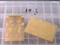
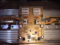
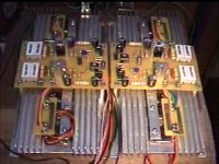
Thought I share this amp to my fellow diyers. Not that hard to build but it sounds good enough for me.
I've tested it with an OPA134 but even an LM301AN will work. Outputs in the prototype are MJL21193/4 (TO-264) but I've tried/tested MJ15003/4, MJ15024/5 (TO-3) with good results. That means it will work with anything you have laying around .
Supply for the prototype is only +/-50V but has also been tested with a +/-70V. If you use the higher supply, better use a bigger heatsink.
Sound is, as I said, good enough for me. I'm planning on using this for mid-high applications but have also tried it for a 10" dual voice coil subwoofer.
JojoD
Thought I share this amp to my fellow diyers. Not that hard to build but it sounds good enough for me.
I've tested it with an OPA134 but even an LM301AN will work. Outputs in the prototype are MJL21193/4 (TO-264) but I've tried/tested MJ15003/4, MJ15024/5 (TO-3) with good results. That means it will work with anything you have laying around
.Supply for the prototype is only +/-50V but has also been tested with a +/-70V. If you use the higher supply, better use a bigger heatsink.
Sound is, as I said, good enough for me. I'm planning on using this for mid-high applications but have also tried it for a 10" dual voice coil subwoofer.
JojoD
Attachments

Congrats JojoD,
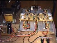
Nice work, I like the way the amps are sat on top of the heatsink with the drivers either side. Also the fact the the heatsink fins are verticle giving the best cooling. When ever I build an amp I always end up with the HS upsidedown or some such poor configuration.
With +-50v its should be good for approx 250Watts into 4 Ohms well within the capabilaties of two pairs of MLJ21193/94.
Happy lisening
jean-paul
hi,
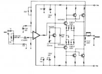
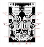
i was too excited to post the amp and forgot to edit the schematic. however, you can find the values of the resistors in the pcb parts placement guide. The values for the caps are at the schematic. Hope you guys don't get confused!
The amp is working and playing as I post this message, it has been four days and still no problem. Anyway, this is actually the second prototype.
Cheers
JojoD
hi,
i was too excited to post the amp and forgot to edit the schematic. however, you can find the values of the resistors in the pcb parts placement guide. The values for the caps are at the schematic.
Hope you guys don't get confused!The amp is working and playing as I post this message, it has been four days and still no problem.
Anyway, this is actually the second prototype. Cheers
JojoD
Did you try local feedback at the opamp and only a DC feedback for offset compensation ?
A long time ago I made amps like that and they sounded better than the conventional way but measured poorer.
Not negatively meant but I would always decouple supply lines with some caps and around the opamps I would place them very near the supply pins. With the more modern opamps a small cap ( 10 to 100 nF ) directly from + to - pins of the used opamp might be necessary.
Apart from that it looks cool.
no tweaking yet...
Nope, I haven't tried tinkering with the feedback since I am still learning the basics. Happily, I can only measure +0.001Vdc at the speaker output. I have to switch the DMM to the lowest dc setting to measure that. Also, I haven't connected the Zobel and the RL on the output going to the speakers.
I haven't measured the output power since I am yet to find where I can borrow an oscilloscope.
Cheers,
JojoD
Did you try local feedback at the opamp and only a DC feedback for offset compensation ?
Nope, I haven't tried tinkering with the feedback since I am still learning the basics. Happily, I can only measure +0.001Vdc at the speaker output. I have to switch the DMM to the lowest dc setting to measure that. Also, I haven't connected the Zobel and the RL on the output going to the speakers.
I haven't measured the output power since I am yet to find where I can borrow an oscilloscope.
Cheers,
JojoD
Hi sajti,
Nice to hear you are also building a similar amp. This amp's sound is worth listening to, nice lows and clear highs. I plan on a biamp setup using my leach amp and this amp.
Maybe you can share your project amp to us when it's finished?
Jean-paul,
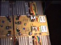
Hi, I did put a 100nf cap on the supply rails of the opamp as can be seen on the pcb parts placement guide. I'll post a more detailed pcb parts placement guide soon...
Regards,
JojoD
Nice to hear you are also building a similar amp. This amp's sound is worth listening to, nice lows and clear highs. I plan on a biamp setup using my leach amp and this amp.
Maybe you can share your project amp to us when it's finished?
Jean-paul,
Hi, I did put a 100nf cap on the supply rails of the opamp as can be seen on the pcb parts placement guide. I'll post a more detailed pcb parts placement guide soon...
Regards,
JojoD
JojoD818 said:Hi sajti,
Nice to hear you are also building a similar amp. This amp's sound is worth listening to, nice lows and clear highs. I plan on a biamp setup using my leach amp and this amp.
Maybe you can share your project amp to us when it's finished?
Regards,
JojoD
I can show the schematic first time. But unfortunately my server is unreachable from USA. I can send the schematic to You, if You can put up ...
Sajti
Killer Amp!!! I am watching the discussion with much interest. May also want to build a version.
Hi,
Please feel free to build your own version and post your comments especially your suggestions on improvements. I am currently considering the use of 4 pairs of output transistors and increasing the supply rails but that will have to wait.
Do you intend to include short circuit protection in this amplifier (VI limiter).
I'll leave that to the other guys who have a much wider experience in such fields.
Cheers,
JojoD
reminds me of daniel meyer
in the late 60's daniel meyer came out with an article in "popular electronics" magazine, 'tigers that roar', then in 1972, he came out with 'tigersaurus' featuring the same output stage as the one you built, even bryston has adapted this design. my experience with this topology is that it is prone to oscillation at high frequency, the output stage trannies heatup even though the bias levels seems to be correct, i would be very carefull with this type of amps, this amp though packs a lot of punch in the low end, thus i would reccomend as suitable for bass speakers, mid and highs are not as good as with leach amps, i would say.....
in the late 60's daniel meyer came out with an article in "popular electronics" magazine, 'tigers that roar', then in 1972, he came out with 'tigersaurus' featuring the same output stage as the one you built, even bryston has adapted this design. my experience with this topology is that it is prone to oscillation at high frequency, the output stage trannies heatup even though the bias levels seems to be correct, i would be very carefull with this type of amps, this amp though packs a lot of punch in the low end, thus i would reccomend as suitable for bass speakers, mid and highs are not as good as with leach amps, i would say.....
- Status
- This old topic is closed. If you want to reopen this topic, contact a moderator using the "Report Post" button.
- Home
- Amplifiers
- Solid State
- My recent power amp...