I put anybody up to the challenge , this is to prove to a job internship person that I did in fact invent 25%-75% of this amplifier . I do not even study in small electronics , i study industrial electronics (automated aseembly chains , process control , motors etc... ) , but i have a passion for small electronics ( scope in room , love tesla inventions , read/study all the time , etc ... )
I have NEVER seen a circuit that is LIKE mine ANYWHERE ON THE INTERNET , you dont have to be a genius to know that you can used an op amp to drive a mosfet anyways... basicly this idea came to me naturally . The choice of op amps were easy , needed good high volts for the high Vgs drop and fast SR for the high Vgs drop + ok current drive... easy choice .
First off I have never seen somebody used my bias method ,using my school notebook ad my logical deductive ability , I knew that for my purpose adjusting all the 12 bias points would be a serious pain in the neck, the point is to cancel any asymetry in Vgs of mosfets that will not be handpicked or matched , the circuit i based my amp on used coupling cap bias ( not as good for my purpose ) and did not use feedback .
This is a major factor since this is a 3 phase amp and many amps are connected to the single bias point on the + of the op amp . The circuit uses a zener regulator and cap to truely settle the bias point to un-moveable voltage level in case i get noise on the power lines ,this was also my idea , an idea to improve ontop of an idea that I never saw is an idea indeed ?
I put anybody to the challenge to find this specific circuit ON GOOGLE OR ON ANY SITE OR ANY OP AMP BUILT WICH REMOTLY USES THIS DESIGN.
I WILL SEND 5$ PAYPAL TO THIS PERSON .
Attachments
Last edited:
Don't give up inventing just yet, but you got some problems...
Needs custom output transformer with less than .008% distortion.
A tiny DC offset at the input can create several Ampres of lopsided
do-nothing current in the output transformer, possibly saturating the core...
Needs balanced input with perfect even split and less than .008% distortion.
Considering V3 input sees 10K input impedance, and the other input 5K???
10K to virtual ground in parallel with 10K to real ground, yeah that be 5K.
Either get rid the 10K to real ground, or make the same for both inputs...
I don't understand why we need 3 power supplies when one will do.
They make op-amps that work from single supply, you know...
If you can't find prior reference to this circuit, its because you didn't search
the vacuum tube forum. Push pull cathode followers a little strange, but not
unheard of... McIntosh did this, though they put half the winding over the
drain (I mean plate) and used to cancel some parasitics in the transformer
and derive screen voltages that made Pentodes act like today's MOSFETs.
http://drtube.com/audioamp.htm#McIntosh
Look up MC60...
Last edited:
There are some distant similarities to other amplifiers:
Power amp by Susan Parker
http://www.diyaudio.com/forums/solid-state/42259-zero-feedback-impedance-amplifiers.html
Preamp by Greg van der Sluys
Classic Valve Design - Original and Legacy Design PCB's
However, there are no similarities to amplifiers at the chip amp forum because your design doesn't contain any power-op-amp. Moderator, please move this thread to the discrete solid state amplifier forum.
Last edited:
Should have made this title . Did I invent this ? And plz give tips to make it better . Cool amp for all to make
thx for all answers , this is free for all to make , plz gives tips on how to make better yes thx ,might still make this one , one day ... one day ...
I gave up making it physically when I saw the price for audio transformers , this was for an invention .
and I thought that I wouldnt saturate the core if the transformer saw approx same current in different directions ... I am confused ?
Last edited:
What garauntees the core sees same current both directions? When you have nothing
up front that eliminates DC offset. Especially between inputs of different impedance...
You have nothing that measures DC current imbalance in the winding.
It takes very little DC to saturate an audio transformer.
They have an absurd number of windings. 20 Henries is not unusual...
up front that eliminates DC offset. Especially between inputs of different impedance...
You have nothing that measures DC current imbalance in the winding.
It takes very little DC to saturate an audio transformer.
They have an absurd number of windings. 20 Henries is not unusual...
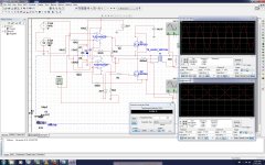
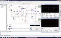
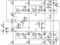
Ok i modded my drawing , the blue dotted square was making it seem confusing
here is the real drawing with parts of dotted square removed .
Well my idea was that the 99.9% similar op amps on the same chip with Gain 2 would regulate the voltage level at the source of mosfet and that would be enough ?
Remember that is just for showing , this is far from optimized , first off my dc levelis way too high , i see about 2 volts dc with 0.5 ohms resistance , thats = to 4 amps static times 2 , I would drop this voltage to about 0.5 volts , but Im busy doing something else , another circuit .
This sim i made long long ago , 1 year ago in fact .
LETS UPP THE ANTEES : I WILL SEND 10$ PAYPAL TO THE PERSON WHO CAN DISPROVE THAT THI DESIGN IS AT LEAST 50% MINE.
Attachments
Last edited:
I say that...
Special pleading.
How about mods merge the two threads over at Solid State?
 I've merged the two threads and left a 1 month re-direct in the chip amps forum and removed the duplicates
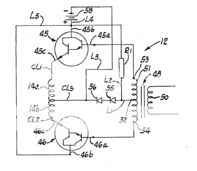
Replace the two bias diodes with an FET bias transistor on the main heatsink.
Replace the output transformer with a dual voice coil subwoofer with 1Ω coils, you now have a cheap and cheerful subwoofer amp for the car, no inverter, no output transformer required.
United States Patent 4,130,725
Nagel December 19, 1978
Last edited:
Yes, the principle has been used since the fifties for solid state amps.
Replace the two bias diodes with an FET bias transistor on the main heatsink.
Transistor Museum Early Germanium Power Transistor History by Joe Knight RCA Page 2
Some used clever tricks to cope with the transformer's imperfection, like a global NFB including the transformer, coupled with a faster local compensation for stability.
You could apply the technique to this amplifier.
You have a rare amplifier that's not a production design.Did I invent this?
One person who can truly answer your question is Susan Parker. She's beautiful, REALLY smart, has the amp that's most like yours, makes transformers by hand, makes some great speakers and is a member of diyaudio.com. Well, just send her a message with your question.
Susan Parker Diyaudio page <-----link
Audiophonics Web Site <-----link
Hi larryB
Output stage from schematic presented is the most common solution in all transformer output stages, no matter if you use tubes, BJT's as driving devices, nothing new.
OP amp driving mosfet cell to cluster, most common solution in PA amplifiers.
Input phase differential stage - classical topology.
All together as a combination - it will work.")
Output stage from schematic presented is the most common solution in all transformer output stages, no matter if you use tubes, BJT's as driving devices, nothing new.
OP amp driving mosfet cell to cluster, most common solution in PA amplifiers.
Input phase differential stage - classical topology.
All together as a combination - it will work.
Attachments
Thx , and thx . I think the intern guy will be impressed , to flatter my ego is secondary of course I never claimed to have re-invented the wheel , I obviously never saw that specific scheme , this was made by me for my needs , if somebody did it before me so be it , but I DID NOT COPY ... I used my schoolbook and my logic , google images gave me a scheme that I modified 75% , yes the amp that I based my amp on was the zeus amp and another op amp version of the zeus amp wich used ac coupling bias , no feedback on both .
I built this op amp with my application in mind the whole time , need a xformer , needed simple bias scheme due to multi phase , needed this somewhat simple , needed this mosfet for durability , needed this class a for querky reactive loads ( impedance unspecified and unknown ) , the amp was thus made opon my very specific and weird needs .
thx all for your contribution .
I never claimed to have re-invented the wheel , I obviously never saw that specific scheme , this was made by me for my needs , if somebody did it before me so be it , but I DID NOT COPY ... I used my schoolbook and my logic , google images gave me a scheme that I modified 75% , yes the amp that I based my amp on was the zeus amp and another op amp version of the zeus amp wich used ac coupling bias , no feedback on both .I built this op amp with my application in mind the whole time , need a xformer , needed simple bias scheme due to multi phase , needed this somewhat simple , needed this mosfet for durability , needed this class a for querky reactive loads ( impedance unspecified and unknown ) , the amp was thus made opon my very specific and weird needs .
thx all for your contribution .
It is a "tubeless amp"
With the concertina replaced with op-amps and the output tubes replaced with fets, you can see half of it in some tube amp designs and you can see half of it in other tube amp designs. This would be a really great invention if one could accomplish the impedance amp function without the hand made output transformer. You know, there are some tube amp designs that don't mandate output transformers. Or, a clever transformer replacement/simulation circuit made with solid state parts? A reason why this couldn't be accomplished is beyond my understanding.
With the concertina replaced with op-amps and the output tubes replaced with fets, you can see half of it in some tube amp designs and you can see half of it in other tube amp designs. This would be a really great invention if one could accomplish the impedance amp function without the hand made output transformer. You know, there are some tube amp designs that don't mandate output transformers.
Or, a clever transformer replacement/simulation circuit made with solid state parts? A reason why this couldn't be accomplished is beyond my understanding.
Last edited:
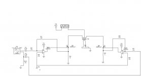
I have done many different versions of a design like yours here are just a couple that I dugg out of my archive of 1000's of files.
Mostly it was inspired by Susan Parkers design and I have simulated both a transistor drive and an opamp drive system.
Either can be biased in class a or B/AB but biasing class A at such high current can be damaging to the transformer core if something should go wrong on one of the output transistor legs.
I had devised this system last year for use on my ESL's as I use a standard toriod transfomer with a couple of added windings for primary's to drive them.
I have not built it yet but it is on my list of things to try.
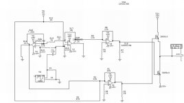
The opamp version that I am showing is not my only version but it is one of the first ones I believe I did then I switched to the transistor version.
I can do some more searching of other versions if you wish as I have a lot.
jer
Mostly it was inspired by Susan Parkers design and I have simulated both a transistor drive and an opamp drive system.
Either can be biased in class a or B/AB but biasing class A at such high current can be damaging to the transformer core if something should go wrong on one of the output transistor legs.
I had devised this system last year for use on my ESL's as I use a standard toriod transfomer with a couple of added windings for primary's to drive them.
I have not built it yet but it is on my list of things to try.
The opamp version that I am showing is not my only version but it is one of the first ones I believe I did then I switched to the transistor version.
I can do some more searching of other versions if you wish as I have a lot.
jer
Attachments
Last edited:
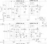
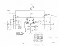
Very cool Lazy cat,I have been kicking around some ideas like you have posted.
In that type of configuration one can add as many output stage they desire as each one is self biased.
Here is a design that I thought I would throw out there as there is so much talk about an amp that doesn't use any negative feed back.
In the sims it works but the FET's would have to be very closely matched.
I had started on this but I haven't done any more with it lately as I have many projects going on right now.
it will be interesting to see what all of you think about this one as It was inspired by a few discussion lately and is something that I have had in the back of my mind for many years now.
jer
Attachments
- Status
- This old topic is closed. If you want to reopen this topic, contact a moderator using the "Report Post" button.
- Home
- Amplifiers
- Solid State
- My invention ? Did I invent this amp ?