Is the schematic accurate for the driving and output stages? The author says it uses a current feedback pair topology. Personally I have always had a dodgy view of CFP for large power amplifiers. But if the drawing is correct, it is strange that they used the mosfet drivers as source follower. The maximum peak that Vout could be is Vcc-Vgs-VR21-VR19. IRF610/9610 are vertical type fets so count on Vgsth at least 3.5V. The bias on these if the intent is class AB operation (IMHO drivers should be class A) should be at least a couple hundred mA, to mitigate the Gm droop of this type of mosfet at low currents, <100mA.
The SMD input cap is not of the right type. Since this has turned into an evaluation thread, electrolytic input cap is a poor choice as well for full range audio. I prefer polypropylene film but a 10uf PPM cap will be physically large. 1uf is a more viable size but the input Z may not be high enough for 1uf and will result in LF rolloff. Perhaps it could be modified but not without knowing what is inside the IPS block in the diagram.
view of CFP for large power amplifiers. But if the drawing is correct, it is strange that they used the mosfet drivers as source follower. The maximum peak that Vout could be is Vcc-Vgs-VR21-VR19. IRF610/9610 are vertical type fets so count on Vgsth at least 3.5V. The bias on these if the intent is class AB operation (IMHO drivers should be class A) should be at least a couple hundred mA, to mitigate the Gm droop of this type of mosfet at low currents, <100mA. The SMD input cap is not of the right type. Since this has turned into an evaluation thread, electrolytic input cap is a poor choice as well for full range audio. I prefer polypropylene film but a 10uf PPM cap will be physically large. 1uf is a more viable size but the input Z may not be high enough for 1uf and will result in LF rolloff. Perhaps it could be modified but not without knowing what is inside the IPS block in the diagram.
Zobel
The 10R + 100nF cap. is the standard and necessary Zobel network or Boucherot cell found in virtually all conventional amp. outputs. Doug Self gives a fair exolanation and examination of the values used. HF oscillation can kill it but not without a fight.
Perhaps the coil shown in your pic. is some more insurance?
I guess the CFP/B design refers to just the shade areas of the schematic as the output stage is EF.
Last edited:
L20 V9
OK, I've measured the voltage across some of the 0.22 Ohm resistors and it 5 - 6 mV's. Thanks for the tip. I should have done it in the first place but everything is so close together I didnt want to risk it. In future I won't rely on the clamp meter at such low currents.
I can't remember exactly what I did but after restoring the circuit to standard (took out the pots), one channel expired. So it's all going on the back burner for a few days whilst I recover .
.
I am now using the 70Vac toroids and because the mains was up around 251Vac, the DC was about 74V and there's nothing I can do about it. I ran it at 50W's both channels and the waveforms looked good except there was a little crossover distortion visible on one channel and nothing I could see on the other.
I am now using my HP N&D set as a source (should have done it in the first place) as the kit built oscillator I was using had it's own waveform problems. The amp. waveforms now look much better. To be continued.
OK, I've measured the voltage across some of the 0.22 Ohm resistors and it 5 - 6 mV's. Thanks for the tip. I should have done it in the first place but everything is so close together I didnt want to risk it. In future I won't rely on the clamp meter at such low currents.
I can't remember exactly what I did but after restoring the circuit to standard (took out the pots), one channel expired. So it's all going on the back burner for a few days whilst I recover
. I am now using the 70Vac toroids and because the mains was up around 251Vac, the DC was about 74V and there's nothing I can do about it. I ran it at 50W's both channels and the waveforms looked good except there was a little crossover distortion visible on one channel and nothing I could see on the other.
I am now using my HP N&D set as a source (should have done it in the first place) as the kit built oscillator I was using had it's own waveform problems. The amp. waveforms now look much better. To be continued.
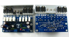
Change a lot. To join the pre-amplifier.
Standard three Darlington structure. A coupling capacitor.
NJW power to change the four pairs tube using ONSEMI to it can achieve 250W 8R.
I named it for the L25.
The preamplifier gain is 4.7 times.
Level after about 25 times.
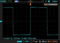
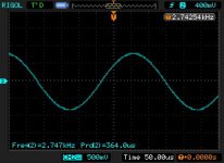
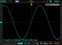
The above is the simultaneous measurement of the input signal sine wave output signal
2012-5-12
Standard three Darlington structure. A coupling capacitor.
NJW power to change the four pairs tube using ONSEMI to it can achieve 250W 8R.
I named it for the L25.
The preamplifier gain is 4.7 times.
Level after about 25 times.
The above is the simultaneous measurement of the input signal sine wave output signal
2012-5-12
Attachments
L20 V9
I purchased two new V9 boards and rebuilt the amp, now using the 500VA toroids (+/-73VDC with 251VAC input). I had trouble again with one channel but it turned out to be an intermittent earth on one RCA input. Tested both channels to 30WRMS into 6 ohms with less than 0.01% distortion measured on my HP N&D set. I have been listening for about three hours and the amp sounds very good and getting better, almost valve like. Not as good as my 845 SET monoblocks which clean it up on clarity and detail but great impact which the SET's couldn't do in a fit. Looks like I will be heading for the metal bashers soon to make the casework.
I purchased two new V9 boards and rebuilt the amp, now using the 500VA toroids (+/-73VDC with 251VAC input). I had trouble again with one channel but it turned out to be an intermittent earth on one RCA input. Tested both channels to 30WRMS into 6 ohms with less than 0.01% distortion measured on my HP N&D set. I have been listening for about three hours and the amp sounds very good and getting better, almost valve like. Not as good as my 845 SET monoblocks which clean it up on clarity and detail but great impact which the SET's couldn't do in a fit. Looks like I will be heading for the metal bashers soon to make the casework.
Attachments
L20 V9
Sorry, I don't know. I pulled the breadboarded amps apart and have almost finished the final versions. If they were finished I could tell you. Anyway, if you put about 10mV RMS AC in at say 50Hz and measure the RMS volts at the output into an 8 ohm load, you can calculate the output power and then the gain. You should be able to extrapolate from there. If you had a CRO it would be easy to measure the signal across the 8 ohm load at clipping and then measure the input with the CRO. Of course you would need a resistive load rated for the expected power. Don't even think about using a speaker!
Sorry, I don't know. I pulled the breadboarded amps apart and have almost finished the final versions. If they were finished I could tell you. Anyway, if you put about 10mV RMS AC in at say 50Hz and measure the RMS volts at the output into an 8 ohm load, you can calculate the output power and then the gain. You should be able to extrapolate from there. If you had a CRO it would be easy to measure the signal across the 8 ohm load at clipping and then measure the input with the CRO. Of course you would need a resistive load rated for the expected power. Don't even think about using a speaker!
Found the problem and saw same on a forum
Low pass audio filter placed after amplifier - All About Circuits Forum
by removing the input capacitor(10uf) the amplifiers started to sound
and quite nice,i should remove the 10k resistor as well
- and of course Replace the 2k2 resistor with a COIL (inductor) and C2 to ,with the calculated value for the 24,5 - 25khz LowPass filter
and bring the input to aprox 6-8V preamplifaction,i dont know the upper limit
that will be normal for high end preamp
the 100k should stay in place because it brings preamp to required input impedance
sO HIGH PASS filter only after amplifier and !! Not Before
- also replaced 1n4007 with ultrafast 35ns diodes ,because 1n4007 limited speed will act as a filter for transistor switching
Last edited:
Got more than 100w,apparently fuses after Thermistors limit the current to the amp
used 200k pot with pseudologarithmic 1k in parallel ,still no highs at low volume
You need a preamplifier.
With it, you can output the greater voltage.
Until close to your power supply voltage, + - 65 v is the ideal value of the output signal.
Premise is you need to input about 1.5 V signal, because the L20 magnification is about 34.
I finally finished my L20 V9 monoblocks today. It's taken over 12 months. There's been a few smoke clouds along the way as per my previous posts. I have to say that they are the best solid state amps I have built so far and are very valve like in their sound. I normally listen through 300B 60W Audiospace monoblocks and the L20's are the closest I've come to bettering them. I still have the problem with high DC rails due to the wrong selection of toroids and high mains voltage and will have to do something about it eventually and that will probably mean buying new toroids.
David.
David.
L20 Kit
Sir,
I also order this kit from ebay and would you please to summary what have you done from input C1 until output may be add a zobel, R feedback, and VDC etc?
Many thanks and regards,
Pamuji
So i finished my amp,videos on youtube
cs4398 dac. So l20 input voltage 6v
sounds loud and clean no distortions or noise
help biasing to class A, 50w is enough
Sir,
I also order this kit from ebay and would you please to summary what have you done from input C1 until output may be add a zobel, R feedback, and VDC etc?
Many thanks and regards,
Pamuji
L20V9
I removed the supplied input capacitors on my monoblock builds and the sound is significantly better. But removing the capacitors is not a good idea if there is any DC on the input signal. Otherwise, the amps are stock standard and I have fitted speaker protection modules. I used new toroids which give +/-56V rails which for me are a lot safer than the +/-73V rails I had with the first toroids. Of course the power is lower but I never use more than about 20W on the loudest passages with my 92db speakers. The L20V9 really does sound very realistic, the bass end is well controlled and the overall sound is very smooth. It could be a little more detailed at the top end when I compare it to my 300B 60W monoblocks but they are a hard act to follow. I'm using 4x10,000uf on each power supply rail plus 10x22uf wound foil caps on each rail. I feel that this 220uf of foil caps on each rail cleans up the top end a little and have used the same idea on other builds. I am using massive heatsinks which are complete overkill and never seem to warm up. However, when the amps have been on for a few hours they do seem to sound a little more detailed and the layering is improved slightly.
I removed the supplied input capacitors on my monoblock builds and the sound is significantly better. But removing the capacitors is not a good idea if there is any DC on the input signal. Otherwise, the amps are stock standard and I have fitted speaker protection modules. I used new toroids which give +/-56V rails which for me are a lot safer than the +/-73V rails I had with the first toroids. Of course the power is lower but I never use more than about 20W on the loudest passages with my 92db speakers. The L20V9 really does sound very realistic, the bass end is well controlled and the overall sound is very smooth. It could be a little more detailed at the top end when I compare it to my 300B 60W monoblocks but they are a hard act to follow. I'm using 4x10,000uf on each power supply rail plus 10x22uf wound foil caps on each rail. I feel that this 220uf of foil caps on each rail cleans up the top end a little and have used the same idea on other builds. I am using massive heatsinks which are complete overkill and never seem to warm up. However, when the amps have been on for a few hours they do seem to sound a little more detailed and the layering is improved slightly.
- Home
- Amplifiers
- Solid State
- L20 V8