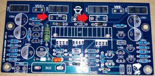
Yes, I think that is obvious. I can't quite believe that a kit was put together and sold with only one pair of emitter resistors for eight output transistors.Each output transistor must have an emitter resistor.
Perhaps I lift all the output power transistor emitter leads and install a 0.12 Ohm resistor between each emitter lead and the pad on the PCB. A little messy but I don't want this amplifier to fail.
Did anyone else buy a V7 L20 and get a kit with only two 0.1 resistors and no individual emitter resistors for eight output transistors???
Attachments
Last edited:
I guess I could go to two pairs of NJW0281G and NJW0302G or 2SC5200N and 2SA1943N. I have 2SC5200N and 2SA1943N. (And I also have some 2SC6145 and 2SA2223.)
But that would be the fourth LJM amplifier that I have had to change the outputs on. (MX50X2 1st, MX50SE 2nd, L20.5 3rd and I don't want the L20 V7 to be #4.)
I was hoping to fire this one up with the supplied transistors and listen to it as designed. I don't want to mess it up (stability, sound, etc).
Well, you already identified one design error on the PCB, indicating it is a fake. There may be more flaws. If you value your time, it is probably better to get some new kits or just PCBs if you can find them - Please let me share this: I got MX50SE from Nobsound (on Amazon), added the customary R/L on the output, stuck them in a box with DC protection and a +/-40V SMPS. Works great, sweet sound and totally quiet when idle, even with my ear at the mouth of a horn/compression driver attached to it - never experienced that before in an amplifier.
these are dual 3 pin power resistors i guess
They are regular single 5W resistors. The other hole is just a via that is used to connect to traces on the back.
Well, you already identified one design error on the PCB, indicating it is a fake. There may be more flaws. If you value your time, it is probably better to get some new kits or just PCBs if you can find them - Please let me share this: I got MX50SE from Nobsound (on Amazon), added the customary R/L on the output, stuck them in a box with DC protection and a +/-40V SMPS. Works great, sweet sound and totally quiet when idle, even with my ear at the mouth of a horn/compression driver attached to it - never experienced that before in an amplifier.
I guess they could be fake. They came with the same components as my other LJM kits (MX50x2, MX50SE, L20.5). Such as the KY series capacitors, the particular manner of laser marking (and molding and lead frame) of the supposed KEC output transistors, the different pinout NCC 5551, etc.
I built the MX50SE also which I like. That is one of the reasons I started this kit.
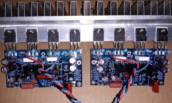
Last night I got as far as a Dim Bulb Tester "first test" with only one pair of outputs, no speaker and just +/- 18V to roughly check for serious faults, offset and bias current. Both fired up and the bias trimmer worked on both. Next I will work on the heatsink and mounting individual emitter resistors on the leads of the output transistors screwed to the heatsink.
The board you have is probably a CFP output based on the drivers and VBE transistors being on the same small heat sink. If it's EF, the VBE transistor would sense the temperature of the outputs, not the drivers. It seems the EF output schematic shown before is not valid for your amp.
It could be a genuine LJM amp, it seems he made a lot of versions with similar names, and he definitely made many CFP amps. Have a look at the LJM L12-2 schematic to get an idea about resistors on a double output CFP.
L12-2 CFP Output amp 120W*2 8R
However, it should probably be ok if you build it as is.
I am going to add emitter resistors as per that L12-2 schematic. I will just lift the emitter leads of the power transistors and solder the emitter resistors between the lifted lead and the pad on the PCB.Have a look at the LJM L12-2 schematic to get an idea about resistors on a double output CFP.
L12-2 CFP Output amp 120W*2 8R
However, it should probably be ok if you build it as is.
Both amps have about 40 mV offset which is annoying since I matched all of the transistors pairs much closer than that. I will try to figure out the cause by probing the emitter resistor pairs in the input section.
The board you have is probably a CFP output based on the drivers and VBE transistors being on the same small heat sink. If it's EF, the VBE transistor would sense the temperature of the outputs, not the drivers. It seems the EF output schematic shown before is not valid for your amp.
It could be a genuine LJM amp, it seems he made a lot of versions with similar names, and he definitely made many CFP amps. Have a look at the LJM L12-2 schematic to get an idea about resistors on a double output CFP.
L12-2 CFP Output amp 120W*2 8R
However, it should probably be ok if you build it as is.
I have added 0.12 Ohm emitter resistors in each emitter (see attached photo). The surgery was not as neat as I would like but it will have to suffice.
Only tried +/-18V with DBT (no speaker, no signal) and both have bias control. Strangely both have about -40mV offset. (Measured -40mV on one and -44mV on the other today.) Since I matched all the small transistor pairs to within +/- 1mV I was not expecting that.
Attachments
The L25 is powerful.Cheers Paladinxxx, nice to know someone has at least powered a pair up all be it for a brief 20 mins before smoke. I would err on the side of caution regarding any performance specifications published with clone modules, usually for "attention-grabbing" purposes. I will use a 50 - 55V supply, not intending to run them up to their maximum output. How did they sound while they were working?
Xslavic, the problem with clone amp modules is that schematics are usually not available and when they are, they have been tampered with or are incorrect. I have collected a batch of likely schematics for the L20 version that are available on this forum but nothing specific to the L25. As I said, the L25 is a modified L20 with an op-amp preamplifier bolted on the front end. That part is easy to deduct, just by looking at the board layout. If the L25 sounds good "out-of-the-box", then I can only improve by removing unnecessary components or reconfiguring as I have done with other clone amplifier modules. I see it as beating the cloners at their own game i.e. cloning the clone
L25 is not L20 + preamplifier.
- Home
- Amplifiers
- Solid State
- L20 V8