Revival
Happy New Year! I have revived this thread after just 6 years. This is regarding the 50 Watt Randy Slone amp.
I finally picked it up off of a pile of junk and started playing with it again. I put a 1 KHz signal through it and hooked it up to my scope and it seems to work. The only thing is, 2 transistors and a resistor get pretty hot. Also, I'm only able to bias it to 33 mV, it's supposed to be at 47 mV. Any higher and the amp starts to run away.
I tested the amp with no input or load, and just left it to run and Q16 got up to 92 degrees C, and Q11 got to around 30 C. Resistor R12 was also getting pretty warm. I took almost all the voltages of the transistors with respect to ground. The resistor voltages were measured across the resistors. Here is a list:
Q1: E = 0.708V, B = 0.086V, C = -36.03V
Q2: E = 0.681V, B = 0.051V, C = -35.84V
Q3: E = 36.6V, B = 36.04V, C = 35.35V
Q4: E = 36.1V, B = 35.43V, C = 0.888V
Q5: E = -36.55V, B = -35.92V, C = -35.94V
Q6: E = -36.64V, B = -36.01V, C = -36V
Q7: E = -36.6V, B = -36.55V, C = -35.95V
Q8: E = -36.59V, B = -35.97V, C = -1.375V
Q9: E = -1.369, B = -0.751V, C = 0.988V
Q10: E = 36.68V, B = 36.36V, C = 35.47V
Q11: E = 36V, B = 35.4V, C = 0.995V
Q12: E = -0.217V, B = 0.088V, C = 1.8V
Q13: E = -0.214V, B = -0.511V, C = -3V
Q16: E = -0.190V, B = 0.349V, C = 36.74V
Q17: E = -0.229V, B = -0.725V, C = -36.7V
R11 = 0.22V, R12 = 0.658V, R1 = 0.084V
Would anybody be able to tell me if these readings are normal for the above circuit in (post 24 page 3) at idle with no load?
Last edited:
Have a look at the circuit traces around Q9.
The sch shows a potentially damaging method for the Vbe multiplier. As shown if the pot wiper lifts momentarily, or permanently, the bias voltage increases massively and could destroy the amplifier due to severe overheating.
You really should change this.
The sch shows a potentially damaging method for the Vbe multiplier. As shown if the pot wiper lifts momentarily, or permanently, the bias voltage increases massively and could destroy the amplifier due to severe overheating.
You really should change this.
Have a look at the circuit traces around Q9.
The sch shows a potentially damaging method for the Vbe multiplier. As shown if the pot wiper lifts momentarily, or permanently, the bias voltage increases massively and could destroy the amplifier due to severe overheating.
You really should change this.
Andrew, it's been too long! I hope you're doing well. I've built a few devices since this project; but this amp has always been in the corner mocking me.
I took a look at all the traces and they physically look good. I pulled a few transistors and measured them with an arduino type component tester. The smaller transistors all measured okay with a Beta around 100. The output transistors were a different story. Q16 measured with a Beta of just 50, while the other one Q17 is 150.
I'm not confident in my bodge wiring skills and don't know if I can modify the circuit without destroying the PCB. The mass destruction previously, was likely caused be the bias transistor not being clamped to the output.
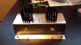
Some loose ends I should mention, the two output transistors aren't thermally connected. They are on separate heat sinks. The bias transistor is clamped to the heat sink of Q17. I might have to build my own heat sink that fits all three. The T03 sinks are all pretty expensive for some reason.
I've made my own hobo heatsink. I put two new T03's on it and installed some grommets. I made it out of a cookie tin. This way it has the added feature of smelling like shortbread if the amp get too hot. haha
I'm still testing the other components, so far so good.
I'm still testing the other components, so far so good.
An externally hosted image should be here but it was not working when we last tested it.
Attachments
Last edited:
Umm... my guess is that you can't feel much heat more than about 10mm from the real heatsinks that may be rated about 8C/W. 'Not much help there with thin sheet steel and the real heatsinks would do better on their own with more free air convection. Look about for a scrap of hobo sheet aluminium, 1.5-3mm thick or should I use the US form aluminum as appropriate in your location?
Last edited:
You guys don't like my heatsink, I'm a bit offended; I cut up a pretty nice cookie tin. j/k.
Ian I'm with the Yanks on the pronunciation of the word aluminum, I don't think I've heard anybody here using the "old dart" version.
Andrew 5mm would be nice to find, it'd be harder to work with though. Cutting and bending etc. I'm going to keep at it with desoldering components and testing them. I can usually hear the amp running away now, because the transformers make a distinct buzzing sound.
Do the two output transistors HAVE to be on the same heatsink, or is that just good practice?
I finished pulling all the transistors and measuring them with the tester, they all measure okay, but have variations in gain according to the tester.
This doesn't really tell me much, I'm just going to have to throw parts at the thing, but I'd like to know if any transistors are partly blown.
Is there a simple circuit I can make to get the continuous current in saturation to see if they're working? The smaller ones are 600 mA continuous, not sure about the other two types.
Haven't given up yet. I've replaced all transistors and Electrolytic caps. Also went through checking all components. The output transistors are no longer getting hot at idle. The bias circuit is still acting a bit unstable though. Q11 and Q8 get pretty hot and then cool down. They keep cycling like this.
From looking over the board I found that power resistors R25 and R24 are 8.2 ohms instead of 8. I think that's all they had when I bought these at the store many years ago. I'm not sure if that would effect things. Also the hookup wires for the bias and output transistors are pretty long. I left them that way for now to make it easier to work on the board.
Would appreciate any advice if anybody has any, I may have to try change the bias circuit like many have suggested.
BJT or bipolar transistors don't partly "blow". You can consider them as all-or-nothing devices like a fuse, other than there can be a cumulative weakening effect called secondary breakdown which is an unlikely concern here. https://en.wikipedia.org/wiki/Safe_operating_area
The 8.2 ohm resistors are standard values and there's no point in searching unobtainable parts to change the value by 2% when they probably have a 5% tolerance anyway.
Long hookup wires are always a concern for stability (motorboating, oscillation). Try to eliminate any wiring including power supply leads, that wander about, picking up noise, amplifying it and adding to your output or even causing damage by supersonic oscillation which of course, you can't hear until the heat and smoke make it obvious. That's where the 'scope helps")
The 8.2 ohm resistors are standard values and there's no point in searching unobtainable parts to change the value by 2% when they probably have a 5% tolerance anyway.
Long hookup wires are always a concern for stability (motorboating, oscillation). Try to eliminate any wiring including power supply leads, that wander about, picking up noise, amplifying it and adding to your output or even causing damage by supersonic oscillation which of course, you can't hear until the heat and smoke make it obvious. That's where the 'scope helps
Last edited:
Excellent, I appreciate your help Ian. I'll shorten the wires, one other thought I had... I don't have a volume control pot on this Amp. I guess I can consider it as being cranked to 11 at all times? That shouldn't change anything when it's at idle with no input?
I could've purchased a good commercial amp for the time and money I've spent, but where's the fun in that? I enjoyed the suffering, and thank all of you for your patience, and knowledge.
I could've purchased a good commercial amp for the time and money I've spent, but where's the fun in that? I enjoyed the suffering, and thank all of you for your patience, and knowledge.
It's not the ultimate way to control volume, but a 20-50k log. pot (a linear type is useless) placed in-line with the input signal will attenuate volume well enough. Visit this site often if you want to learn a few tricks as well as the whole audio electronics story made easier for average guys.
Go to figure 6 here for the basic implementation but take your time with the rest of the article for interest and background. As it's just a basic idea, a 10k resistor in each of the in and out connections will help make it more user-friendly and prevent damage.
Go to figure 6 here for the basic implementation but take your time with the rest of the article for interest and background. As it's just a basic idea, a 10k resistor in each of the in and out connections will help make it more user-friendly and prevent damage.
It's not the ultimate way to control volume, but a 20-50k log. pot (a linear type is useless) placed in-line with the input signal will attenuate volume well enough. Visit this site often if you want to learn a few tricks as well as the whole audio electronics story made easier for average guys.
Go to figure 6 here for the basic implementation but take your time with the rest of the article for interest and background. As it's just a basic idea, a 10k resistor in each of the in and out connections will help make it more user-friendly and prevent damage.
Thanks for the link, that was a good read. I think I've got a 20 or 50k log pot around here somewhere.
I've shortened the leads and using the current limiting PS everything seems good so far. Q5 and Q11 still get pretty hot but aren't failing. I might add mini heatsinks to them.
I'll definitely read around the site a little more, to get background info. I spend most of my time on RC aircraft forums, but I've always found electronics interesting, and like to learn.
- Status
- This old topic is closed. If you want to reopen this topic, contact a moderator using the "Report Post" button.
- Home
- Amplifiers
- Solid State
- 12 Watt amp, guidance required