TTC 5200
I haven't been around for a while due to work commitments, nor have I had a chance to read the preceeding few posts. I have just purchased 4 pair of MJL3281/1320 and some A970/C2240 and some BC546/56 for my L20.
I might have been better to buy the pair of pcb, If there were one available!
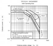
Here is the SOA of the TTC5200's and I see that they have very low current capacity for the voltages that I want to run, i.e. 50 each way.
Cheers.
I haven't been around for a while due to work commitments, nor have I had a chance to read the preceeding few posts. I have just purchased 4 pair of MJL3281/1320 and some A970/C2240 and some BC546/56 for my L20.
I might have been better to buy the pair of pcb, If there were one available!
Here is the SOA of the TTC5200's and I see that they have very low current capacity for the voltages that I want to run, i.e. 50 each way.
Cheers.
Attachments
Cheers
I get it, the speaker is only a few ohms and not a piece of fencing wire!
This can only be a good thing; as I have always looked at the 'DC' line of the graph and tried to stay within it's boundary, meaning that my output transistors are usually under-stressed. [provided I use a 'speaker' on the output terminals!].
On the other hand: When I come to think of it, the 25 degree transistor-case scenario is an ideal. The size limitation of my heat-sink (if it 'is' to fit within a case inside my lounge room!) will substantially reduce the SOA once again.
If the L20V9 I ordered last month doesn't turn up this week, I intend to use my MJL's for a 100W amp based on Mr.Self's Blameless.
@~97Vce
But your output device can only have this Vce (from +-50Vdc) if it is driving a very reactive load with a very out of phase signal. This necessarily reduces the duration from DC to maybe around 10us to 10ms, not DC.
I get it,
the speaker is only a few ohms and not a piece of fencing wire!This can only be a good thing;
as I have always looked at the 'DC' line of the graph and tried to stay within it's boundary, meaning that my output transistors are usually under-stressed. [provided I use a 'speaker' on the output terminals!].On the other hand: When I come to think of it, the 25 degree transistor-case scenario is an ideal. The size limitation of my heat-sink (if it 'is' to fit within a case inside my lounge room!) will substantially reduce the SOA once again.
If the L20V9 I ordered last month doesn't turn up this week, I intend to use my MJL's for a 100W amp based on Mr.Self's Blameless.
I get it,
This can only be a good thing;
On the other hand: When I come to think of it, the 25 degree transistor-case scenario is an ideal. The size limitation of my heat-sink (if it 'is' to fit within a case inside my lounge room!) will substantially reduce the SOA once again.
If the L20V9 I ordered last month doesn't turn up this week, I intend to use my MJL's for a 100W amp based on Mr.Self's Blameless.
I am going to give it a miss, There are no instructions with the kit and the pcb does not match the components shown.
Hi I emailed Jimjim to ask him about tranformer size. Would it be very stupid with a 1000 w 34 VAc trafo for each channel or should it be enough with 500 W for each channel. I have four 500 w 33 vac transformers.
Anybody know if it will be 3 ohm stable with 48 vdc supply ?
Jimjim answered on a completly other question then i asked I think
Anybody know if it will be 3 ohm stable with 48 vdc supply ?
Jimjim answered on a completly other question then i asked I think
You are asking the wrong question...........Anybody know if it will be 3 ohm stable with 48 vdc supply ?..........
If you plan to use 4ohms speaker then the question is:
Will it be stable with a reactive 4ohms load?
A follow up question would be:
Will it be able to deliver enough current from the PSU to the Speaker to allow a 4ohms reactive speaker to be driven properly? This last has little to do with amplifier stability.
A test that you can do is to measure the maximum unclipped voltage into 8ro and 4r0 and 2r0 and 1r0
Then graph the Voltage results as dBV and see where they suddenly drop off.
That drop off which could be at -1dBV or -2dBV relative to 8r0 dBV
The load for this lower output voltage will give you a clue to how well the amplifier delivers current into lower loads.
A 4ohms capable amplifier should easily drive a 2r0 load and very good 4ohms capable amplifiers will drive a 1r0 to high output voltages for a few seconds until the heatsink begins it's fairly fast warm up towards output stage destruction.
Last edited:
Well I do not need that kind off answer.
Funny that one channel is getting hot and the other not without any load at all. Leads are indentical in both channels.
Now I am sure because I measured no bias in one channel. This is going to be difficult to fix because off no schematic.
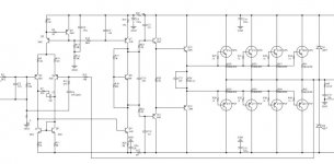
Got this last full schematics
input up to 1.5V RMS
still got some DC
A bit different compared to my 9,2 version. Diffeerent drivers and mine has no resistors on base of output transistors. Mine gets very hot . Maybe oscillates a bit. Have very low dc less than 7 mv.
I modified a bit to get the bias up.
how did you do that ? i have a lot of cooler,doesnt get even warm to touch
i guess it was about r17 and r18 default is 4k7 and 1k .
I have same 9.2 version.please tell me how to bias.
can C13 have another value?
L20SE ,L20 VER9.2
There will be some heat.
If you want to reduce quantity of heat. Reduce the static current.
Reduce 9 k1 resistance, the use of 8K5 OR 8K2
OK
got it so R1 from Voltage divider bias of 669 2SD669 should be lower than the default
Might be because a batch production of parts D669 VCE voltage than a slightly higher in the test.
So to make the static current.
I then to purchase the product batch number. Correct L20SE without debugging.
After installation of static current about 18 to 25 ma. A transistor.
If the static current is greater than this value. Can be adjusted by 9 k1 resistance.
To reduce the resistance value.
hello
where the amplifier l20 se instead of fixed resistor variable resistor soldered ivystavit Quiescent 100mA? Can I replace the output transistors on the other?
Increasing the resistance 9K1 can increase the quiescent current.
Transistor can be replaced by the same type.
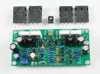
Now the use of TTC5200 TTA1943, they are very good. And the new name makes it no fake
Attachments
- Home
- Amplifiers
- Solid State
- L20 AMP。use only two NJW0302G