I have an amp that has a rather unfortunate design to power the coil of the protection relay. It feeds the 12V relay coil from the +75V rail via a large 1K 5W resistor. The ground of the relay is controlled by a switching transistor. Because the 5W resistor is dissipating so much heat (nearly 4W by my calcs), it occasionally unsolders itself from the board! The odd thing is that there is a +15V rail running right next to the relay. I'm thinking of removing the resistor and replacing it with a 3.3V zener from the +15V line (which feeds from the same transformer as the +75V rail, just different windings). Is that feasible? What would be behind the original idea of powering the coil from the main rail rather than a lower voltage one? I would guess failure of some sort but in most cases I would think the 15V rail should fail at the same time.
These are just opinions - my initial reactions thinking out loud.
The current demand of the relay from that 75v rail is miniscule - at least to the 75v rail. The same milliamps from the 15v rail would be a much more substantial portion of available current. 15v rails tend to serve more sensitive stages in the circuit, so any relay noise might be more pronounced.
Although this only monitors the +75v rail (May I assume this is a split supply and not single rail?), A loss of that rail would result in your expensive speakers not connected to the circuit. A loss of 15v could leave an unguided 75v stage connected to your speaker. I didn;t articulate that very well, hope you could see where I was going with it.
Supplies can fail for many reasons. If a 15v suply is derived from the 75, then loss of 75 means loss of 15. If they run from separate windings, then not. But loss of a rail is not necessarily because the basic supply is absent, a burnt or broken pc trace can lose it, as can a burnt open resistor. So you can have a situation where both 75 and 15v rails exist, but one makes it all the way to the circuit and the other does not.
No need for a zener, just calculate a resistor.
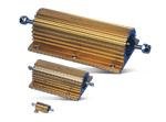
And instead of re-engineering, consider a larger resistor. In pro audio we encounter a certain model line of Fender amps with under-spec'd resistors in a zener supply that like to unsolder themselves. SOme guys replace the on-board resistors with a pair of those aluminum Dale type 25 watt resistors bolted to the chassis with wires back to the board. You could mount one of those off to the side. As a larger resistor with integral heat sink, it will be less of a hot spot, plus bolted to the chassis it will cool itself better.
From mouser, under $3
The current demand of the relay from that 75v rail is miniscule - at least to the 75v rail. The same milliamps from the 15v rail would be a much more substantial portion of available current. 15v rails tend to serve more sensitive stages in the circuit, so any relay noise might be more pronounced.
Although this only monitors the +75v rail (May I assume this is a split supply and not single rail?), A loss of that rail would result in your expensive speakers not connected to the circuit. A loss of 15v could leave an unguided 75v stage connected to your speaker. I didn;t articulate that very well, hope you could see where I was going with it.
Supplies can fail for many reasons. If a 15v suply is derived from the 75, then loss of 75 means loss of 15. If they run from separate windings, then not. But loss of a rail is not necessarily because the basic supply is absent, a burnt or broken pc trace can lose it, as can a burnt open resistor. So you can have a situation where both 75 and 15v rails exist, but one makes it all the way to the circuit and the other does not.
No need for a zener, just calculate a resistor.
And instead of re-engineering, consider a larger resistor. In pro audio we encounter a certain model line of Fender amps with under-spec'd resistors in a zener supply that like to unsolder themselves. SOme guys replace the on-board resistors with a pair of those aluminum Dale type 25 watt resistors bolted to the chassis with wires back to the board. You could mount one of those off to the side. As a larger resistor with integral heat sink, it will be less of a hot spot, plus bolted to the chassis it will cool itself better.
From mouser, under $3
Attachments
Thanks for the reply. I can see what you are saying and that is why I thought it was designed this way. This way the relay opens when the big rail fails rather than assuming a failure mode that encompasses the 15V rail. I suggested the zener because that is what I have on hand but I could do a heatsinked power resistor as well. I can even see scorch marks on the PCB so I think I'll bolt the heatsink to the chassis well away from the board. Glad to know its not an unknown issue amongst power amps.
I like Zeners because they don't seem to complain when run at near Pmax.
400mW 15V Zener will pass 20mA all day.
A string of 4 (costing a few cents/pence) will drop 60V and still supply sufficient current to the relay.
The relay switching can be changed slightly to use the 15V for fast and positive turn on. Then reduce to ~ 7V to consume less current. This keeps the relay and the Zeners much cooler. This usually only needs an extra capacitor and resistor.
I like Zeners because they don't seem to complain when run at near Pmax.
400mW 15V Zener will pass 20mA all day.
A string of 4 (costing a few cents/pence) will drop 60V and still supply sufficient current to the relay.
The relay switching can be changed slightly to use the 15V for fast and positive turn on. Then reduce to ~ 7V to consume less current. This keeps the relay and the Zeners much cooler. This usually only needs an extra capacitor and resistor.
An R and C in parallel with each other and then in series with the coil to give it enough initial switch-on voltage and then drive it with 7 volts DC? Not a bad idea, I may test that out on the relay. Unfortunately, at 12V the coil draws about 50mA so I would have to get 1W zeners since I don't have them on hand. 4 cents each from what I can tell!
then use 6 10V Zeners to drop 60V. or whatever combination you need. It don't need to be 60V. 48V or 50V or 56V would all work.
The extra resistor is in series with the relay coil. The extra cap is in parallel with the series combination of Transistor switch and relay coil, i.e. the resistor is outside the cap loop.
The extra resistor is in series with the relay coil. The extra cap is in parallel with the series combination of Transistor switch and relay coil, i.e. the resistor is outside the cap loop.
- Status
- This old topic is closed. If you want to reopen this topic, contact a moderator using the "Report Post" button.