If you're looking for something tried and tested, check out this one:
More detail (and PCB) available at:
300/500W Subwoofer Power Amplifier
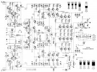
By coincidence, I found the one below yesterday. Looks interesting, but I don't know anything about it. Except that it could be from Elektor (as seen in the schematic style).
An externally hosted image should be here but it was not working when we last tested it.
More detail (and PCB) available at:
300/500W Subwoofer Power Amplifier
By coincidence, I found the one below yesterday. Looks interesting, but I don't know anything about it. Except that it could be from Elektor (as seen in the schematic style).
Attachments
Last edited:
At these powers your better off buying a commercial PA amplifier.
High power amplifiers are only for the experienced as they involve dangerous voltages.
Also the parts you need will cost about as much if not more than a off the shelf amp. Just the transformer which for a 500W amp would be around 1-2kVA will alone cost about as much as a readymade amp.
High power amplifiers are only for the experienced as they involve dangerous voltages.
Also the parts you need will cost about as much if not more than a off the shelf amp. Just the transformer which for a 500W amp would be around 1-2kVA will alone cost about as much as a readymade amp.
...first we are not supposed to post directly esp schematics ...
even though rods circuit is a work horse and if designed and used properly is actually a very good amplifier given the simplicity is made .
the P68's i 've made working more than 3 years continuously and absolutely flawless at 95% of the power for more than 12 hours a day ( powers a subs in a movie theater )...
Still this amplifier features no protection and if abused will eventually fail ..... design properly will mean pcb from esp
as about elektor circuits even though in simulation might work ...in real life it will be a nightmare to stabilize ...
Apex circuits s a very nice option i think ....
500W is about the limit of what is sane in a conventional class B amplifier. My guess is that a commercial PA amplifier in this class will either be class D or unaffordable. Not that there is anything wrong with class D, mind you. It is a lot more efficient, which helps to keep the weight down for one (less transformer and heat sink needed). But how does ultimate sound quality compare? Maybe somebody in the know can comment on this.
Tekko is on to something. A quick look on Yahoogle turned up this beast for $450 + shipping.
Gemini XP-6000 Professional 6000W Amplifier
It is rated at 600Wpc into 8 ohm with 0.1% THD. That's a lot of power for the bucks.
Is it possible to beat this price in a DIY class B project?
You will need two 1000VA transformers:
And two (no, make that that four) 0.3K/W heat-sinks:
Lots of these:
And don't forget these little suckers:
By now we have blown the $450 and the shopping list is still quite long...
An externally hosted image should be here but it was not working when we last tested it.
Gemini XP-6000 Professional 6000W Amplifier
It is rated at 600Wpc into 8 ohm with 0.1% THD. That's a lot of power for the bucks.
Is it possible to beat this price in a DIY class B project?
You will need two 1000VA transformers:
An externally hosted image should be here but it was not working when we last tested it.
And two (no, make that that four) 0.3K/W heat-sinks:
An externally hosted image should be here but it was not working when we last tested it.
Lots of these:
An externally hosted image should be here but it was not working when we last tested it.
And don't forget these little suckers:
An externally hosted image should be here but it was not working when we last tested it.
By now we have blown the $450 and the shopping list is still quite long...
Last edited:
any behringer EP2500 or EP 4000 will easily put 500 W per channel in to a resistive load of 8 R at 1Khz sine ..
problem is that it will not put exactly the same in inductive or real life load
cost of EP4000 is bit more than 300 euros
Then again ... 500w in class AB is walk in the park to make ...i can tell you more than 20 people that can easily create schematics of even more power ...
How well the schematic is implemented and how well the amplifier is protected from it shelf or against all the well known PA abuse is a totally different game ...
now ... from schematic to a product is a very loooooong way but not in sane Ingenius ....
Maybe insane is too strong a word for a 500W+ class B amp. ")
But what do you say about something that generates 600W of output power and 200W or more of heat? About the same as a 200W class A push-pull amp, and there are not many of those around.
It is possible, but not something to undertake lightly. I have managed to come up with a schematic for such a thing. It's not that hard. Take an existing design, up the PSU rail voltages a bit and keep adding output devices until you are in the SOA. It's fun to simulate it in LtSpice, but I'm not planning on building one soon. The currents involved approach that of an arc welder. Especially if you want to drive a 2 ohm load.
To illustrate my point, here is a pic of a Krell KSA200. The heatsinks are about right, but the power supply can only deliver about half the current needed for a 600W class B amp.
An externally hosted image should be here but it was not working when we last tested it.
Last edited:
no problem ingenious you may ask and learn from people that constructed class AB for 500 or more watts as i did .... or simply follow some of the existing nice threads regarding this issue ...one i think is the Dirty Harry ...nice work and very well documented i think
sakis
sakis
Thanks for the tip on Dirty Harry.
http://www.diyaudio.com/forums/solid-state/97566-powerfull-amplifier-named-dirty-harry.html
A good read. A picture of the power supply would have been nice.
http://www.diyaudio.com/forums/solid-state/97566-powerfull-amplifier-named-dirty-harry.html
A good read. A picture of the power supply would have been nice.
Could you explain your reasoning for arriving at that conclusion?.........the power supply can only deliver about half the current needed for a 600W class B amp.[/IMG]
Could you explain your reasoning for arriving at that conclusion?
First - two assumptions. A class A push-pull amp is 50% effective and a class B amp is 75% effective. I know the theory says 78%, but let's keep the math simple.
Therefore, a 200W class A amp puts out 200W of heat. Likewise, a 600W class B amp also puts out 200W of heat. The heatsink requirements for the two amps are therefore identical. The class B amp's power supply has to deliver 800W, double that of the class A amp.
Disclaimer: The above may be over-simplifying things, as is my use of the Krell KSA200 as an example.
I understand what you have stated.
I do not agree with much of what you have stated. Some of it is simply wrong.
A theoretically perfect and ideal, ClassA Push Pull amplifier running on +-40Vdc supply rails and the output stage biased to 2.5A can in the ideal case output 40Vpk into an 8r0 load requiring 5Apk of ClassA current. That is 100W into 8r0.
The quiescent dissipation of that idealised ClassA amplifier is 200W.
At maximum ClassA output the efficiency is 50%. We are agreed for the idealised case.
In the real situation the supply rails are more likely to be +-50Vdc and the output bias around 2.6A and the voltage amp stages drawing a further 100 to 200mA.
The quiescent dissipation for a real 100W into 8r0 ClassA Push Pull amplifier is approximately 265W. This results in an efficiency of zero at quiescent state and a maximum of ~38% when delivering maximum power. Approximately 165W is dissipated by the heatsinks and warmed air circulation.
Now consider a real ClassAB 100W into 8r0 speaker with supply rails of +-50Vdc and a quiescent current of about 150mA. 100mA of bias through the output stage and 50mA of bias for the voltage amplifier stage. The quiescent dissipation is around 15W.
This results in zero efficiency at the quiescent state, exactly the same as the real ClassA amplifier considered earlier.
When delivering full power the total consumption will be 5Apk (or about 3.54Arms) per rail on a 50% duty cycle plus roughly half the quiescent current, but at 100% duty cycle. Total consumption is approximately 185W. The resulting efficiency is ~54%. Of that total consumption only ~85 W is dissipated during maximum power delivery.
That, when summed over a typical music spectrum & period, tells you how much electrical power you use when running these two types of amplifier.
It tells you absolutely nothing about peak current capability comparisons of the two amplifiers.
It certainly does not tell you that the two respective heatsinks must be the same.
Last edited:
output transistors
thing. It's not that hard. Take an existing design, up the PSU rail voltages a bit and keep adding output devices until you are in the SOA. It's fun to simulate it in LtSpice, but I'm not planning on building one soon. The currents involved approach that of an arc welder. Especially if you want to drive a 2 ohm load.
hi ingenieus
greetings for 2 ohms load what output transistors are you planning to use and what rail voltage are you going to use
warm regards
andrew lebon
well .... Andrew's point of view is more or less the same with you ingenious ....As far As i know Andrew is a teacher so he is way too good on calculating things and he actually saved many in the forum from critical mistakes , including my sorry a** and if i remember well that should be way over and more than once ... ( thanks Andrew !! )
In real life though and in commercial amplifiers things are not exactly like that ....
the use of multistage VI limiters , input limiters marginal transformers and ventilation will present more useable results while preserve the safety of the amplifier .Can this be called hifi ? i presume not then on the other hand your calculations and Andrew's most of the time are correct and probably will produce a "more" hifi amp.
question one will be how much "hifi" is required in such an application IE 500W rated at 8 ohms
question two this obviously takes us to my first point of view that schematics for rated power of 500 ore more watts are very possible to find but implementation of the schematic and completing it with protections in every stage against PA abuse is what is actually missing from the original schematics .
Thank you
Sakis
Sakis,
I don't know how you interpreted my comments.
Upto
I don't know how you interpreted my comments.
Upto
after that everything is completely different. I cannot seen any agreement nor similarity in our approaches to understanding what is going on !!!!We are agreed for the idealised case
greetings for 2 ohms load what output transistors are you planning to use and what rail voltage are you going to use
warm regards
andrew lebon
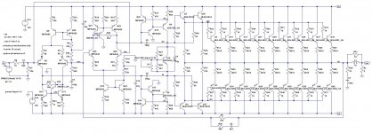
I have been doodling in LTspice with such a thing to see what is possible, but I am not building one. Don't have the funds, the time or the need for a 600W amp.
For output devices, the MJL4281 and MJL4302 work well. For ultimate performance. i.e. collector current not in the dreaded beta droop zone, about 10 of each is needed to drive a 2 ohm load (but you can get by with fewer of them). For 120V rails, output power is 3000W into 2 ohm, with THD at 0,0028%. Output current is about 55A by the way.
The input power is about 6kW, so we are nowhere near the theoretical efficiency - as predicted by AndrewT. This level of power is already somewhat beyond the power available from a normal 230V wall socket. I've seen a 3000W electrical heater melt its plastic plug to the socket when left on full blast for too long.
I present the schematic here, but it is nowhere nearly ready to be built. There are no VI limiters, for one. I haven't done any open loop analysis on it yet. The power supply is just two neat little symbols. In real life there would be a huge transformer, huge diode bridge, huge capacitors and huge relays to protect it all. Just taming the inrush current is a scary prospect!
Attachments
Last edited:
- Status
- This old topic is closed. If you want to reopen this topic, contact a moderator using the "Report Post" button.
- Home
- Amplifiers
- Solid State
- 500W RMS PA Amplifier