Why then could a switch mode sound so good? Well they are designed to switch fast and has a lot of energy stored in the capacitors, normally a lot more energy than in a low voltage supply. Think about it a 1000uF cap at 315V stores roughly the same energy as a 40 000uF cap at 50V. Besides the 1000uF cap will dispense the energy 40 times faster than the 40 000uF and therefore respond to transient requirements 40 times quicker. Makes you wonder....
PCB updates
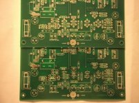
Having received no updates for improvement so far I speed-ed up the progress and had the boards cut today. The boards will arrive next week. Thus those to receive complementary boards should receive them the week after. So get your components and oscilloscopes in order.
Having received no updates for improvement so far I speed-ed up the progress and had the boards cut today. The boards will arrive next week. Thus those to receive complementary boards should receive them the week after. So get your components and oscilloscopes in order.
Hi Joel,
I'm using LT1083 which is good up to 7.5A current. Peak current is 9A. Max dissipation is 60W. I have 5V drop voltage. Apex only does 5A.
you are using ic that regulates the voltage how about the current?usually a high current regulated power supply uses big transistor like in amplifier.Have you seen apex regulated power supply?
I'm using LT1083 which is good up to 7.5A current. Peak current is 9A. Max dissipation is 60W. I have 5V drop voltage. Apex only does 5A.
How much current?
How much current do I need for 8 ohms reactive load (speaker)?not enough current...
What is the peak instantaneous output voltage?
Use the formula:
Imax ~ Current Factor * Vpk / Speaker nominal impedance.
Current Factor can be around 2 for a mild reactance speaker using music that does not contain very fast starting signals nor very fast stopping signals.
Current Factor can be as high as 5 for "normal" reactance speakers when the music does contain very fast starting signals and/or very fast stopping signals.
I adopt CF=3 for my designs.
Assuming 40Vpk & 8ohm speaker.
Imax ~ 15Apk
This is a short term current peak that causes no significant heating of the output devices nor of the heatsink above the operating temperatures.
Last edited:
Hi,
the smoothing capacitance and the local decoupling supply these transients.
The faster the transient the higher proportion comes from the local decoupling.
The transformer will not see any significant transient demand. It's job is to recharge the smoothing when the mains voltage is high enough to send current around the charging circuit.
These are fast transients as far as using the CF is concerned. I would guess the slowest would be <10ms but more likely ~100us or much less. That is why they have very little in the way of heating effect.
Where they do affect design is in the output devices, the driver devices, the pre-driver devices if fitted and the VAS.
The high transient output current ripples back through the previous stages. Design to meet these current demands.

What is the peak instantaneous output voltage?
Use the formula:
Imax ~ Current Factor * Vpk / Speaker nominal impedance.
Current Factor can be around 2 for a mild reactance speaker using music that does not contain very fast starting signals nor very fast stopping signals.
Current Factor can be as high as 5 for "normal" reactance speakers when the music does contain very fast starting signals and/or very fast stopping signals.
I adopt CF=3 for my designs.
Assuming 40Vpk & 8ohm speaker.
Imax ~ 15Apk
This is a short term current peak that causes no significant heating of the output devices nor of the heatsink above the operating temperatures.
The output stage must be able to reach the estimated Imax with a sufficient amout of current gain. Even though 40V/8R is 5A, the circuit should be able to deliver 15A in short duty. And of course AC gain varies inversely proportional to frequency.

Bias
Last couple of days I’ve been experimenting with different bias values. I went from 50mA up to 230mA, that is from 13mV across emitter resistors up to about 50mV. I didn’t go higher because I was afraid to fry the output transistors.
I found that the sweet spot for me is between 100mA and 200mA. Going higher that 200mA actually made the sound worst, less smooth. 50mA (13mV) is way too low and I could perceive distortion. At 100mA (23mV) the sound is much more smooth and “liquid” than at 50mA. Going higher than 100mA the sound increases in smoothness but is not a night and day difference. Somewhere about 150mA seems where going higher I couldn’t perceive any difference, except that higher than 200mA things change again but for worst sound. I have now the SYMEF biased at 150mA (33mV) and I think it will stay this way.
Drownranger, did you try different bias values? What is your perception?
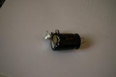
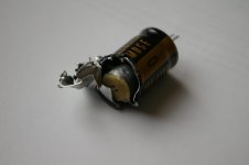
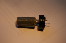
Incidentally, I soldered a Muse KZ capacitor the wrong way and it became very hot and inflate the top. I wanted to see what’s inside so I opened the can. It then vented a vapor smelling like sulfer. I took some pics of what’s inside and here they are:
Last couple of days I’ve been experimenting with different bias values. I went from 50mA up to 230mA, that is from 13mV across emitter resistors up to about 50mV. I didn’t go higher because I was afraid to fry the output transistors.
I found that the sweet spot for me is between 100mA and 200mA. Going higher that 200mA actually made the sound worst, less smooth. 50mA (13mV) is way too low and I could perceive distortion. At 100mA (23mV) the sound is much more smooth and “liquid” than at 50mA. Going higher than 100mA the sound increases in smoothness but is not a night and day difference. Somewhere about 150mA seems where going higher I couldn’t perceive any difference, except that higher than 200mA things change again but for worst sound. I have now the SYMEF biased at 150mA (33mV) and I think it will stay this way.
Drownranger, did you try different bias values? What is your perception?
Incidentally, I soldered a Muse KZ capacitor the wrong way and it became very hot and inflate the top. I wanted to see what’s inside so I opened the can. It then vented a vapor smelling like sulfer. I took some pics of what’s inside and here they are:
Attachments
nope...
hi Paulo,
I just stayed at 46mv. across two resistor emitter.theres something I read in books about gm doubling.when you try to bias a class b output as same as class a.besides my heatsink could not handle more heat.height is 3.75" which is very small.
regards,
joel
p.s.
next time be aware of the polarity and stick to safety region.
- Home
- Amplifiers
- Solid State
- SYMEF amplifier