Hi Nikosokey,
This amplifier is based on a formula that says that you will like it. However the formula needs more validation by having a large number of respondents giving feedback. We are exploring beyond stability and T.H.D. This amplifier should also be the most stable amplifier not only in this forum but in the world.
If you are looking for adventure and are willing to share your experiences please join us for an unforgettable experience")
kind regards,
Harrison.
This amplifier is based on a formula that says that you will like it. However the formula needs more validation by having a large number of respondents giving feedback. We are exploring beyond stability and T.H.D. This amplifier should also be the most stable amplifier not only in this forum but in the world.
If you are looking for adventure and are willing to share your experiences please join us for an unforgettable experience
kind regards,
Harrison.

hi Harrison,
you are right in your simulation it shows 10mv but in real world much lower up to 4mv.and also I have change the decoupling capacitor fro 33uf to 220uf even at full volume no hum can be heard.
as you can see my input or signal wires is not shielded and no need coz the amp.is quiet and also used copper tube as spacer for the pcb and connection of my star gnd. to chassis.
in listenning test, surely it has beaten my carver receiver .I have used a behringer mixer with low ,mid and high contol and to control the volume of the signal because I did not put a volume contol on the amp.I compare the symef to my carver coz it has also high ,mid and low contol.
symef turned my tower speaker(yamaha) sounds like a big speaker.voice of the artist sounds big and the bass is very good even at low volume.I really like the mids and lows of this amp. thats why its sounds very natural to me.
thank you so much for this amplifier.I am very satisfied with this amp.it is really worth of my money,time and energy.Now my worries are over the amp. is working and sound is excellent.
thanks, harrison .I do love your symef amp. now.It is a treasure!
regards,
joel
I have quoted Drow, who is a pioneer capable of grabbing bull by horns
. I have done this for those of you looking for a different kind of motivation other than adventure.What will be your experience ?
kind regards,
Harrison.
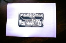
Thank you but the printout is very big, what's the zoom scale factor for printing right?here it is now and goodluck to your amp.
Thanks.
size is correct.
you can use alex mm if that is big for you but the output is not a flat pack.If you gonna use my board no need for L bracket.I use L bracket co'z my heatsink is divided into three.and beside it,board is already tested
regards,
joel
p.s. just print it.I uploaded the correct and exact size.right now I could not give you the size its in my room,tomorrow.
Last edited:
So it's right or 30% larger?I have also printed out revision 1 by Alex. Its 30% larger.
I was thinking about redesigning the pcb in a smaller footprint but leaving everything more or less the same way. What do you mean by different schemes of thermal compensation?Are you looking for a smaller footprint ? It may require different schemes of thermal compensation.
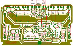
Something I like in your layout is the big pads. Are you using Eagle? If you are, how do you get the nice pads? I use Eagle and the standard pads are way to small and the drill almost eats them remaining only a smal portion of copper. The way I work around this is by placing bigger vias on top of the parts pads but this is not a nice solution. Your pads are very good!
Are you using Eagle? If you are, how do you get the nice pads? I use Eagle and the standard pads are way to small and the drill almost eats them remaining only a smal portion of copper. The way I work around this is by placing bigger vias on top of the parts pads but this is not a nice solution. Your pads are very good!a picture
Hi Paul,
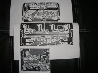
Here a picture. The top one is Drows, the one he has tested and is using. The middle is by Alex with TO3s. The bottom is 1DIFFQC by Alex.
By thermal compensation I meant that the predrivers and drivers could be rearranged to squeeze in the PCB, however a way to thermal track will be needed.
kind regards,
Harrison.
Hi Paul,
Here a picture. The top one is Drows, the one he has tested and is using. The middle is by Alex with TO3s. The bottom is 1DIFFQC by Alex.
By thermal compensation I meant that the predrivers and drivers could be rearranged to squeeze in the PCB, however a way to thermal track will be needed.
kind regards,
Harrison.
Attachments
Hi OnAudio,
Thanks!
Hi drowranger,
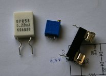
If is not to much trouble could I ask you to do a little redesigning in order to accommodate the 0.22R power resistors, the inline pins trimmer and a smaller fuse older as in the picture, please? Thank you.
Yes, you're right!Your printer is alright . Take a semiconductor and try to place it in its location on the paper It should fit.
Thanks!Hi drowranger,
If is not to much trouble could I ask you to do a little redesigning in order to accommodate the 0.22R power resistors, the inline pins trimmer and a smaller fuse older as in the picture, please? Thank you.
Attachments
Sorry, I shouldn't have asked you this, it's up to me to do my work for my parts. Maybe it will be a good learning exercise of Eagle. I have only designed very simple boards and it's time to evolve and learn more. So far I have drawn the schematic with my parts and tomorrow I'll start layouting the pcb. I'll use your board as reference, the idea is just to replace the parts that have a different layout (KOA resistors, trimmer and fuse holders). Everything else will be as in your nice board.If is not to much trouble could I ask you to do a little redesigning in order to accommodate the 0.22R power resistors...
ok...no problem
Hi Paulo,
I used RE 5watts that was in my board because that was easily available in my country.In my latest board check pin configuration of trimmer co'z I already change it with diff.pot, pin configuration is in triangular form like in you picture.
I will change the resistor(emitter)and and fuse holder to suit your taste.
regards,
drowranger
p.s.
sorry for taking time in answering your request I only have internet, in my office. saturday I will present it to you.latest size of board approximately 6"x3.5".
- Home
- Amplifiers
- Solid State
- SYMEF amplifier