Early HV Regulator
OK, not a JDSR. This is from Jim Williams second application note:
Will probably look better than anything you can build with an AD825.
OK, not a JDSR. This is from Jim Williams second application note:
An externally hosted image should be here but it was not working when we last tested it.
Will probably look better than anything you can build with an AD825.
Jan,
Thanks for the info. I'm afraid power amps need more than a few 10s mAs to work properly, even on low current stages.
I also read worrying things about the TL783, after my initial excitement about its existence. Can't quote where here, but it seemed to have "oscillation bursts" that were even difficult to find.
After a "research" I did looking for likely designs this medium voltage application, I was between a Salas shunt regulator and an improved 3X7 reg. But I think this HV Jung reg might be a very good third choice.
What would be an appropriate zener at the IC output for 60 to 70volts?
Carlos
Jan,
Thanks for the info. I'm afraid power amps need more than a few 10s mAs to work properly, even on low current stages. [snip]Carlos
Carl, the '10's of mA referred to the supply of the error opamp in the reulator. The regulator itself could supply as much as you reasonably want.
The zener in series with the opamp output in the Jung/Didden reg is there to bridge the voltage difference between the pass device base (which is close to Vout) and the output of the opam, which you want to stay ideally at mid-supply (opamp supply that is).
So with a (separate) opamp supply of say 24V and Vout of 60V, you'd use a zener of 47V which is a standard value.
As 'bursts of oscillations' is concerned, that may be the case if you want to wrap such a reg in a feedback loop but used as they normally are used, this doesn't happen if you use the recommended cap at the output (you DO read the data sheet, right
") ).
).jan
OK, not a JDSR. This is from Jim Williams second application note:
An externally hosted image should be here but it was not working when we last tested it.
Will probably look better than anything you can build with an AD825.
... or for really high voltage 500V or 1 kV, use my T-Reg
jan didden
Attachments
Quite an accomplishment that HV Jung version!
I imagine that you set the output voltage with R11/R12 and the IC voltage with R9/R10, right?
For the regulator output, if Vref is 6.9v, then R11 should 1K for 144v, me thinks.
My interest is because I'm considering several regulator designs to use on the low-current regulators on my power amps, which now use 3X7 types and I would like to improve on them. But I didn't know how to get to use Jung/Didden regs for my voltages, which would be +/- 60 or 65 volts, or even 70.
Would these regulator design be an "exaggeration" on such application?
Carlos
Hi Carlos
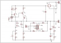
The error amp supply floats with the output voltage because the TL431 reference is the regulated output. It is set by R9 and R10 (currently 32 volts) while R13 sets the idle current for the TL431.
Vref zener has to stay within the supply rails of the opamp. + is 140 volts and - is 108 volts. Vref should be somewhere in the middle of that.
Jan, feel free to add anything to this.
Carl, the '10's of mA referred to the supply of the error opamp in the reulator. The regulator itself could supply as much as you reasonably want.
Oh, I thought you were talking about the LR8 (which in fact can only feed up to 10mA) or the TL783. The 783 can handle up to 700mA.
I just googled the 783 again, and one of the comments I had found was was from this forum:
http://www.diyaudio.com/forums/chip-amps/115980-tl783-hv-reggy.html
The chip made noises when it was turned off apparently.
The zener in series with the opamp output in the Jung/Didden reg is there to bridge the voltage difference between the pass device base (which is close to Vout) and the output of the opam, which you want to stay ideally at mid-supply (opamp supply that is).
So with a (separate) opamp supply of say 24V and Vout of 60V, you'd use a zener of 47V which is a standard value.
Do you mean I'd have to use a separate 24v supply for the chip? Then it wouldn't fit what I want.
Once I considered using the only high voltage chip I know, the OPA445, as a direct replacement on the Jung/Didden supply for my purposes. Would that chip do? Would that make a better regulator?
As 'bursts of oscillations' is concerned, that may be the case if you want to wrap such a reg in a feedback loop but used as they normally are used, this doesn't happen if you use the recommended cap at the output (you DO read the data sheet
No, the oscillations were on a regulator using the TL783.
Carlos
Carl, the '10's of mA referred to the supply of the error opamp in the reulator. The regulator itself could supply as much as you reasonably want.
The zener in series with the opamp output in the Jung/Didden reg is there to bridge the voltage difference between the pass device base (which is close to Vout) and the output of the opam, which you want to stay ideally at mid-supply (opamp supply that is).
So with a (separate) opamp supply of say 24V and Vout of 60V, you'd use a zener of 47V which is a standard value.
As 'bursts of oscillations' is concerned, that may be the case if you want to wrap such a reg in a feedback loop but used as they normally are used, this doesn't happen if you use the recommended cap at the output (you DO read the data sheet, right
jan
Hi Jan
With regards to my mods, maybe it would be better to reference the TL431 to ground so a low voltage precision voltage reference can be used on the + input of the error amp, then a large zener can go on the output of the error amp to bridge the difference between the pass device??
Here is an updated schematic with the TL431 tied to ground and a 125 V zener on output of error amp. Vref is also much smaller so a precision zener can be used.
Seems like a good plan. Maybe decrease the values of R3 and R10 so that the ref terminal of the 431 sees a nice low impedance. Also use a cap on the output of that 431, and probably a good idea on the input as well. IIRC the data sheet specs a value for that to ensure stability.
Edit: R14 and R15 are also pretty high valued. Having such large values sourcing the -input of the opamp invites problems with parasitic capacitances. I understand you want to keep the curren drain and dissipation low, but it's a trade-off.
jan didden
Last edited:
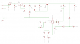
diezel - that looks great. I tried a 'similar' approach but couldn't get it work properly. It was for a tube preamp at 160v. Your schematic seems to perform well on my simulator. Is it possible to get 160v from it easily?
Rob
Hi Rob
In theory you could get 160v out of it. you would need the zeners on the output of the error amp to add up to 145 volts (providing that the opamp is biased midway at 15 volts).
Thanks for the suggestions Jan, I will update. I was trying to keep the current down but you are right.
Hi Rob
In theory you could get 160v out of it. you would need the zeners on the output of the error amp to add up to 145 volts (providing that the opamp is biased midway at 15 volts).
Thanks for the suggestions Jan, I will update. I was trying to keep the current down but you are right.
One possible problem to watch out with those high voltage versions is that 150V zeners are not really 'good' zeners. They can have several k-ohms dynamic impedance. That means that their zener voltage varies a lot with current and you need to make sure that the Vout of the opamp doesn't get out of the max limit and/or too low for regulation. Depends also on the load current (the opamp current is the load current/ pass device gain). I haven't done any calculations but probably a good strategy is to make the no load opamp current relatively high, so that the variation is not as big, and then select a good zener. Or make a synthesised zener that has low impedance and can be precisely adjusted. There's a ton of circuits for it on the 'net.
jan didden
- Status
- This old topic is closed. If you want to reopen this topic, contact a moderator using the "Report Post" button.
- Home
- Amplifiers
- Solid State
- Hi voltage Jung super reg