Those differential pairs were just crying out for current mirror loads, so I added them. The THD at 20kHz is about a quarter of what it was before. The frequency response is fine for a sub amp, but I opened it up a bit for general purpose use. With some tweaking and optimization of values there might be some more improvements forthcoming.
Another thing - it might be better to use a MOSFET for thermal tracking. I'm not sure that a BJT Vbe multiplier goes well with MOSFETs. Does anybody have an opinion on this?
As designed , it wont work correctly , moreover with a darlington VAS.
The subject was much discussed by Olivier73 in a thread by there.
The thread that wahab has in mind I think.
http://www.diyaudio.com/forums/soli...ror-image-topology-construction-troubles.html
http://www.diyaudio.com/forums/soli...ror-image-topology-construction-troubles.html
The balance in the original circuit is quite good. It was more like an itch that needed scratching, but current mirrors does seem like a good idea. A current mirror in an LTP increases open loop gain by 6dB or more and doubles the slew rate.Interesting Ingenieus,
How did you conclude that the diff pair needed the current mirrors? Do you compare the collector current in both legs, or what do you use as trigger to go for a current mirror?

Concerning the vbe multiplier, as I explained in post #1 ,I will be using a 2SK2733 mosfet, but due to the lack of the spice model for this,...
Most MOSFET amps seems to use BJTs for temperature compensation. The Crescendo Millenium Edition is one of the few designs that uses a MOSFET. As far as I know anyway.
Last edited:
As designed , it wont work correctly , moreover with a darlington VAS.
The subject was much discussed by Olivier73 in a thread by there.
As I understand it this doesn't work:

The current mirror in my post above is the solution suggested by Bob Cordell.
There is a third way:
http://www.diyaudio.com/forums/solid-state/99252-my-new-mini-class-amp-5.html#post1413451

I have to admit that I haven't figured it out yet...
Last edited:
You could try the IRFBF20 instead. It looks similar according to the datasheets, but your mileage may vary.The vbe multiplier used in the schematic will be replaced by a 2SK2733 Fet multiplier (have no spice model for that one).
Here is a SPICE model for it:
*Apr 07, 2010
*Doc. ID: 90338, Rev. A
*File Name: part irfbf20_sihfbf20_PS.txt and part irfbf20_sihfbf20_PS.spi
*This document is intended as a SPICE modeling guideline and does not
*constitute a commercial product datasheet. Designers should refer to the
*appropriate data sheet of the same number for guaranteed specification
*limits.
.SUBCKT irfbf20 1 2 3
**************************************
* Model Generated by MODPEX *
*Copyright(c) Symmetry Design Systems*
* All Rights Reserved *
* UNPUBLISHED LICENSED SOFTWARE *
* Contains Proprietary Information *
* Which is The Property of *
* SYMMETRY OR ITS LICENSORS *
*Commercial Use or Resale Restricted *
* by Symmetry License Agreement *
**************************************
* Model generated on Aug 24, 00
* MODEL FORMAT: SPICE3
* Symmetry POWER MOS Model (Version 1.0)
* External Node Designations
* Node 1 -> Drain
* Node 2 -> Gate
* Node 3 -> Source
M1 9 7 8 8 MM L=100u W=100u
* Default values used in MM:
* The voltage-dependent capacitances are
* not included. Other default values are:
* RS=0 RD=0 LD=0 CBD=0 CBS=0 CGBO=0
.MODEL MM NMOS LEVEL=1 IS=1e-32
+VTO=3.76924 LAMBDA=0.00213011 KP=0.909147
+CGSO=4.78811e-06 CGDO=1e-11
RS 8 3 0.000109332
D1 3 1 MD
.MODEL MD D IS=3.94829e-11 RS=0.0258228 N=1.2185 BV=900
+IBV=0.00025 EG=1 XTI=2.95262 TT=0
+CJO=4.39396e-10 VJ=2.09658 M=0.9 FC=0.5
RDS 3 1 1e+06
RD 9 1 7.39653
RG 2 7 1.94714
D2 4 5 MD1
* Default values used in MD1:
* RS=0 EG=1.11 XTI=3.0 TT=0
* BV=infinite IBV=1mA
.MODEL MD1 D IS=1e-32 N=50
+CJO=1.22208e-09 VJ=1.01441 M=0.9 FC=1e-08
D3 0 5 MD2
* Default values used in MD2:
* EG=1.11 XTI=3.0 TT=0 CJO=0
* BV=infinite IBV=1mA
.MODEL MD2 D IS=1e-10 N=0.816578 RS=3e-06
RL 5 10 1
FI2 7 9 VFI2 -1
VFI2 4 0 0
EV16 10 0 9 7 1
CAP 11 10 1.22208e-09
FI1 7 9 VFI1 -1
VFI1 11 6 0
RCAP 6 10 1
D4 0 6 MD3
* Default values used in MD3:
* EG=1.11 XTI=3.0 TT=0 CJO=0
* RS=0 BV=infinite IBV=1mA
.MODEL MD3 D IS=1e-10 N=0.816578
.ENDS irfbf20
The thread that wahab has in mind I think.
http://www.diyaudio.com/forums/soli...ror-image-topology-construction-troubles.html
That s it...
As I understand it this doesn't work:
The current mirror in my post above is the solution suggested by Bob Cordell.
There is a third way:
I have to admit that I haven't figured it out yet...
The current mirrors bring improvements but a reproducible
implementation is not that trivial.
Surely that Bob s solution works although that s quite a lot
of complexity.
Anyway , as already said , an amp dedicated to feed a subwoofer
will have inherently low THD since NFB will be quite efficient at
those frequencies , and a crescendo like amp , with compensation,
seems to me the best option.
The output impedance of the cascoded VAS is comparatively high cf. a Follower.
Most Designers that suggest the cascode also say you must lower that output impedance by using a Follwer after it.
Since there is no separate driver stage. The Crecendo is flouting those design recomendations.
Even D.Self who adopts the double EF as a VAS says there are attractions to using the cascoded VAS + EF.
I believe the current mirror only becomes effective, if both sides of the LTP are fed and loaded symmetrically.
I further believe that this may be the reason that resistor loading is preferred to mirror loading when sound quality is uppermost in the priority list.
Andrew how do you conclude this, most High end amps I have been fortunate to view the insides and turning out of the factories nowadays are using current mirrors. They are built for sound quality as some of them are in cost range from 5000 to 25 000 euros. Take for instance from the Marantz stable, around 5000 euros, chocabloc full of current mirrors and they sound excellent. Another good example is Lavardins newer series, this amp is right on par and better at somethings than my electrocompaniet which costs more then double the price. To my ears it even sounds better than a well known french tube amp manufacturer which turns amps costing around 30 000 euros. Looking at reviews in the press they seem to agree with me, little do they know whats on the inside. High feedback bad......., take a close look at the Lavardin.
Its all myth, every manufacturer looks at trying to fool potencial clients into believing some circuit part is bad and why his amp is better, one has to consider here, not necesarily better, just different.
Last edited:
The output impedance of the cascoded VAS is comparatively high cf. a Follower.
Most Designers that suggest the cascode also say you must lower that output impedance by using a Follwer after it.
Since there is no separate driver stage. The Crecendo is flouting those design recomendations.
Even D.Self who adopts the double EF as a VAS says there are attractions to using the cascoded VAS + EF.
I agree. The cascode VAS creates a transimpedance amplifier, changing the input current X current gain into the output voltage. There are great advantages to this but variations in cascode VAS current create voltage related distortions, which must go back through the loop and so on. Less distortion is better.
I believe the current mirror only becomes effective, if both sides of the LTP are fed and loaded symmetrically.
I further believe that this may be the reason that resistor loading is preferred to mirror loading when sound quality is uppermost in the priority list.
which part? :Andrew how do you conclude this,
I believe
mirror becomes effective if
LTP symmetrically loaded
LTP symmetrically fed
sound quality difference
Quasi amplifier for beginners?!
Hello!
Why amplifier for the subwoofer is so expensive when you have a mosfet IRFP240/IRFP9240 or IRF250 etc,.... rather than those expensive 2sk/2sa!???
It does not have the subwoofer amplifier to be a High-End?
It should be the simplest amlifier to about 200 .. 300W(rms)!
(See topic APEX Audio of Mr. Mile Slavkovic)
Cheers
Hello!
Why amplifier for the subwoofer is so expensive when you have a mosfet IRFP240/IRFP9240 or IRF250 etc,....
rather than those expensive 2sk/2sa!???It does not have the subwoofer amplifier to be a High-End?
It should be the simplest amlifier to about 200 .. 300W(rms)!
(See topic APEX Audio of Mr. Mile Slavkovic)
Cheers
Last edited:
which part? :
I believe
mirror becomes effective if
LTP symmetrically loaded
LTP symmetrically fed
sound quality difference
I agree that mirrors will be more effective objectively when there is symmetry, yet it also works in designs, objectively and subjectively where there isnt symmetry involved, a good example is Lavardin which uses highly tweaked Lin circuits and huge amounts of feedback which of course is another big no no but yet their amps sound superb.
And all this for the amplifier for the subwoofer-please let!!??I agree that mirrors will be more effective objectively when there is symmetry, yet it also works in designs, objectively and subjectively where there isnt symmetry involved, a good example is Lavardin which uses highly tweaked Lin circuits and huge amounts of feedback which of course is another big no no but yet their amps sound superb.

The output impedance of the cascoded VAS is comparatively high cf. a Follower.
Indeed, I was struggling with that also the last days, that's wy I'm gonna use a driver stage (probably FET, 2SK2013 + 2SJ313)
Regarding the quasi topology; don't no wy, but it'n not attractive to me, maybe it's not symmetrical enough
I really love those symmetrical designs (it's something in my head)
And all this for the amplifier for the subwoofer-please let!!??
I had to weight my words better when choosing a good thread name.
Yes, this amp will be used for a sub, BUT, I also wan't to try a new topology for me, this to compare and to learn, for off course the next project.
And this, will for all of us DIY'ers a never ending story.
time for a review
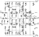
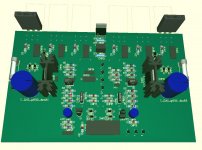
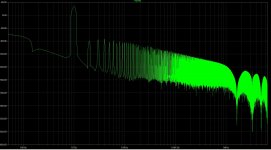
I've choosen for the standard VAS and a driver stage. The cascoded VAS doesn't bring any advantage at the low frequencies for a sub amp.
Please have a look at the attachments:
1 Schematic
2 Phase margin plot, phase margin is +-84°
3 PCB layout (orange = ground)
4 PCB in 3D (done with Target 3001, max 250pins, that's wy only 2 output devices are drawn)
5 FFT plot 1Khz at 150Wrms in to a 4Ohm Load
All comments are welcome.
Attachments
Help with choosing driver FET
I'm doubting which FET to choose for the driver stage.
I've both the 2SK216/2SJ79 as the 2SK2013/2SJ313 in my collection.
Driver stage Parameters:
1: load is 3Pair of 2SK1530/2SJ201 FET's
2: Diver stage idle current = +-25mA
3: Power dissiplation in one FET = +-2.2Wpeak
For schematic: see previous post.
Can anyone give me some help choosing the best of the above two pairs?
The 216/79 pair has very low capacitances and could be used as VAS imo, the 2013/313 look more like real drivers.
To bad that spice models for he 2013/313 are not excisting.
Thanks in advance
Attachments
- Status
- This old topic is closed. If you want to reopen this topic, contact a moderator using the "Report Post" button.
- Home
- Amplifiers
- Solid State
- Amp design for subwoofer and wideband duty