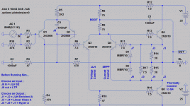
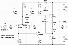
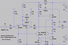
Actual current source here is obviously the bootstrap.
But we can regulate this by shunting away excess bias.
One of the things that has always bugged me about JLH
current steering into 2N3055 , was that it takes a LOT of
bias to fully turn one of those dinosaurs. Way more than
needed for linear class A through the middle.
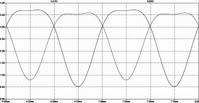
You can see what normally happens with JLH in the 1st
graph "Enriched A". Any shunt regulation here is disabled,
and an old fashioned constant current is steered in the
traditional JLH way. These outputs are running silly hot!
SRPP alone could be used as a phase splitter, but this is
not whats happening here today. It is merely regulating
the sum of output currents. Watch the currents, and you
can see JLH steering in time with the negative going peak.
SRPP shunting in time with the zero crossings at twice
the fundamental frequency.
Whats really going on here is TWO feedback loops acting
in quadrature. Global negative feedback we are already
familiar with, controlling the output stage voltage. Then
we have this new feedback, controlling and shaping the
output stage currents. Voltage and Current feedbacks
cooperating at 90 degree angles of intended effect.
Note: the sim won't run properly untill you connect one
or more output stage shunts. Select an Output Class..
Attachments
Last edited:
One other trick of note: Stiffened dynamic resistance
of the tail by injecting 1/11th of the bootstrap wiggle.
just slightly less than global negative feedback.
---------------
We got six transistors here, vs bootstrap'd JHL four.
But same count as JLH with typical constant current.
Q4 upgrades the bootstrap to smart shunted source.
Q2 is merely correcting offset that most JLH suffer.
Q2 and Q4 can easily be put to sleep with shunts
J1, J2, ans J8. Reverts to the original JLH topolgy.
More or less, as Q2 is still helping to correct offset.
Regardless which flavor of output is selected, I
think it works better with Q2 dumbed down to a
diode. LTP loses half open gain to no advantage.
------------
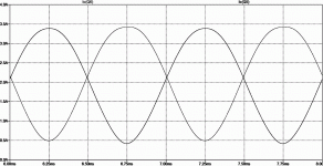
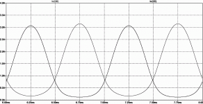
Also intersting that all three modes are class A.
No transistor ever turns off, and all three have
similar current maxima and minima. Yet there is
a huge difference quiescent current depending
on which curve is selecetd. 3A, 2A, 1A.
We are talking 50W heat+ per step backward
toward using constant current source for bias.
Last edited:
Interesting concepts, but I fail to see what the main feature of the circuit (Q4, I think) brings objectively.
OK, it shapes a certain crossing profile, but that's essentially a matter of taste, it contributes to thermal stability, which is good but not essential for class A, but other than that, it seems to degrade the objective, quantitative results from a purely numerical point of view.
This is a first level assessment, I am probably missing a thing or two.
The best objective result would probably be the 2nd case, linear class A.
Where we hold the voltage span across two sensing resistors a constant.
Yet I can see the currents of the 2nd graph are not quite perfectly linear.
Still a heckuvalot more linear than JLH defaults. Steering a constant sum
of drive currents into a pair of imperfect and possibly mismatched legacy
power devices does not result in constant sum of output currents!!! JLH
current nonlinearity takes almost the same shape as the non-switching
Hyper-A case. Merely invert Hyper-A curves, make far less smooth, and
100W hotter, with no protection from runaway, you have traditional JLH.
We show this behavior is manageable, and quite easily too. I would steer
those interested in a JLH project towards Linear A at 50W power savings.
Shunt regulation gives us output device automatching within reason, and
some runaway protection. Linear A also gives us the most constant load
upon the power supply.
Last edited:
Whoa... Just spotted that I had simmed with 2n3019 output devices...
Was supposed to be 2n3055. Might obtain completely different result?
Where was my mind when I posted with the wrong transistor???
--------
No biggie, 2n3055's, adjust bootstraps to 39R and R12 to 3.9R.
JLH curves no longer worse than Hyper-A, merely inverted, and hot...
Linear and Hyper A work best with 33R in the boot and R12=3.3R.
Throw the shunt a few extra mA to steal, so it won't shut off..
Beware JLH mode runs absurdly hot with 33R bootstraps.
Attachments
Last edited:
I simplified a few things for clarity.
Six transistors, no problems...
Kenpeter
I am your fan
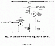
Lets talk a few minutes about precedents found within JLH's original work.
In Fig 10 from 1969, we see a primitive form of shunt regulation for bias.
The only real issue holding this one back is high part count. And perhaps
assumptions that output currents were already linear compliments, rather
than force them to be so. This circuit can't sense what the lower output
transistor is doing, and makes assumptions on the basis of linear class A
rules, that unwatched beta drooping output transistors almost certainly
do not follow.
If this were allowed to reduce quiescent to meet Linear Class A rules,
there would not be enough drive current for either output transistor to
reach the rail under Enriched Class A rules (way JLH actually behaves).
The long time constant of 100u4V will still be restricting base current
more than necessary during peaks. Such restriction was only required
(and remembered on that cap) during the quiescent state...
Totally fixable, and with 5 less parts, no big deal...
Where you sense the current can make all the difference.
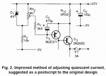
-----------------------------
Then we can look toward Fig2 from 1996. We see again transistor
dumbed down to a constant current source by placing a long time
constant cap across VBE, and the forward VBE drop abused to
make that CCS regulate. Same sensing location and assumptions
as 1969, still suffers all the same issues previously mentioned.
I just move his circuit to the feedback path, and abuse it to fix
offset instead. In that role, it works much better.
Attachments
Last edited:
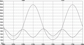
Let me show you the cooperative relationship between
JLH current steering vs SRPP current thieving.
You can see JLH splitting phase in time with the music.
And SRPP shunting away excess bias in time with zero
crossings. No phase splitting happens within this SRPP,
its function is pure shunt regulated push pull.
These two transistors are working completely different
tasks, and don't have to match. They are not a "pair".
If I sometimes draw them as-if a pair, only for art...
----------
JLH regulates the DIFFERENCE of output currents
to create a specified voltage. 11 times input. Yes,
this amp goes to 11, somehow that's important...
SRPP regulates the SUM of output currents to
create a specified current profile. In this case, we
have specified that profile will be Linear Class A.
Since my chart is B/W, know the big wave is JLH.
The smaller wiggle is pure SRPP, no phase split.
Ok, there's maybe 10mA phase split in the SRPP.
A drop in the bucket compared to JLH's 240mA,
clearly the dominant phase splitter here.
Attachments
Last edited:
Something disturbs me with your latest batch of circuits: turning off the correction improves (apparently) the performances.
With Q2 in active service, the THD is ~0.2%, highish for a 3-stage class A.
When Q2 is replaced by a fixed 66mA I-source, the figure becomes 0.07%: more normal and typical for that kind of topology.
OK, raw THD is not everything, but it is an important indicator, and it is one of the first level "compass" or satnav in audio design.
Something over 0.1% @1Khz is clearly excessive.
Even if the correction improves "things", it cannot do so by pushing the overall THD too high
Attachments
Hmmmm... Thieving from underneath doesn't increase overall distortion.
It actually goes down slightly to 0.06% . But this topology adds one
more transistor I'd rather not use. Pretty sure this way exposes Q3
to power supply ripple, but I'm not yet sure if thats a problem.
Current in Q3 is bent by thieving same like before, only now the other
direction. What gives??? Why should thieving from the emitter distort
the final output so much less than thieving from the collector?
You don't suppose its just that Q4 is now held constant at 20mA?
Or is it that current minimum in Q3 increased from 20mA to 60mA?
Or that the burden of parasitic thieving shifted from Q6 to Q5?
Attachments
Last edited:
I just tried even handed thieving with simulated current mirror.
Better than collector thieving not as good as emitter thieving.
Q3 has a definite preference for emitter thieving. More so than
left alone with bias thief disabled.
Why Q3 prefers this parasitic bend, and why in that direction?
Better than collector thieving not as good as emitter thieving.
Q3 has a definite preference for emitter thieving. More so than
left alone with bias thief disabled.
Why Q3 prefers this parasitic bend, and why in that direction?
The current thief seems to create a structural gain imbalance between the top and bottom halves.
If the bottom gain is reduced further with an emitter degeneration, it is possible to take the THD down to 0.025%.
There might be an issue with Q2 too: it has strong residual collector current modulation.
If the bottom gain is reduced further with an emitter degeneration, it is possible to take the THD down to 0.025%.
There might be an issue with Q2 too: it has strong residual collector current modulation.
Attachments
The Q2 collector current *IS* purposely modulated.
To suit the sum of 2n3055 base currents w. droopy
curves figured in. Not necessarily sign of a problem.
We don't want Q2 inter-modulating any quadrature
feedback with the in-phase feedback, just split the
in-phase and pass the quadrature without splitting.
A better transistor here would help, but I'm sticking
to choices JLH had available for the moment.
The 1W distortion is like 0.005% at this point, and
PSRR is -80db at 10K. (with 3R9 + 1000uF low pass
added to the high side, before the bootstrap). The
low side didn't need anything PSRR wise....
May not show up in .four 1K, but do the right click
FFT on V(OUT), you will see both 10K and 15K noises
down about the same -80db as the 2nd harmonic.
Same noise amplitudes as would have produced 1W
into 8 ohms, if injected at the input.
-----------------------
Why is R13 best at 0.3R? I tried raise or lower, but
you have already given the optimum value. I would
have expected 0.18 or 0.36 to match Q5, but no...
Another thing weirds me. Dropping R9 to 8.2R makes
collector current at Q5 a lot more symmetrical to Q6.
But makes .four 1K distortion a lot worse... I don't
get why this pair prefers to be imbalanced?
Do you think a non-polarized 1uF should bypass the
C2 + C3 series pair? Are -2V peaks bad where only
+0.66V of polarizing bias exists? Do I want more?
Attachments
Last edited:
OK, but I fail to see the fundamental, underlying reasons there: C3 will introduce a big phase shift, both C3's esr and and Q2 dynamic resistances are small, not very well defined and will compete, and the effect will have a slope of -6dB/octaveThe Q2 collector current *IS* purposely modulated.
To suit the sum of 2n3055 base currents w. droopy
curves figured in. Not necessarily sign of a problem.
The .four statement can be extended to any rank, see version f.May not show up in .four 1K, but do the right click
FFT on V(OUT), you will see both 10K and 15K noises
down about the same -80db as the 2nd harmonic.
Same noise amplitudes as would have produced 1W
into 8 ohms, if injected at the input.
-----------------------
R13 compensates for an as yet unidentified asymmetry hidden somewhere.Why is R13 best at 0.3R? I tried raise or lower, but
you have already given the optimum value. I would
have expected 0.18 or 0.36 to match Q5, but no...
Another thing weirds me. Dropping R9 to 8.2R makes
collector current at Q5 a lot more symmetrical to Q6.
But makes .four 1K distortion a lot worse... I don't
get why this pair prefers to be imbalanced?
That asymmetry has probably already been partially compensated elsewhere, and the remainder has an odd value.
If you look at the currents into the 0.18R resistors, they are symmetric.
The base current from the top transistor also contributes to the output.
Even the current to the bootstrap cap has an effect, depending on where you pick the signal up.
NoDo you think a non-polarized 1uF should bypass the
C2 + C3 series pair?
I don't see where the -2V are coming from?Are -2V peaks bad where only
+0.66V of polarizing bias exists? Do I want more?
Attachments
OK, but I fail to see the fundamental, underlying reasons there: C3 will introduce a big phase shift, both C3's esr and and Q2 dynamic resistances are small, not very well defined and will compete, and the effect will have a slope of -6dB/octave
OK,
I do not understand,
but why the 10th harmonic is so high?
- Status
- This old topic is closed. If you want to reopen this topic, contact a moderator using the "Report Post" button.
- Home
- Amplifiers
- Solid State
- Shunt Regulated JLH
