Member
Joined 2009
Paid Member
Drilled holes in one steel L bracket; is that news?
I am still puzzling over simple mechanical details.
Lamer of the century award...
If I sandwich the output transistors between the
L and the copper backside of my board (maximum
heat dissipation), I might want to flip the pinout on
my layout. Else I have to build the whole circuit on
the backside. I don't know how well the islands will
stick to the copper side? I was planing to superglue
the bare side of my Mahattan pads to the bare side
of the board. I've seen it done on the copper side,
but I don't know if attachment is sturdy like that..
-----
No, I just need to drill holes to let the output legs
feed through the board to the bare side, without
touching the groundplane as they pass through...
BD139 fullpack isn't same thickness as 2SC5200.
How do I shim the sandwich to insure it touches
the L bracket of the heatsink? Or is just sticking
it between groundplane and L bracket adequate?
Only needs to sense output heat, not dissipate
much of its own...
I find the building part takes ages for me too, I have 3 projects half way through. Included is my JLH 10W which has all the power devices on the heatsink - I've decided to wait and see how your prototype goes because I like your circuit a lot and may adopt this for my final version.
Maybe you could mount the power devices to the L bracket and run short wires to the pcb, a couple of inches shouldn't be an issue - allowing you maximum flexibility whilst you prototype this circuit. It'll make it easier to replace things when you blow them up - which can happen when you're doing something new. BD139 can likewise by fly-wired to the pcb.
I did it!!!
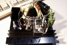
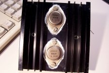
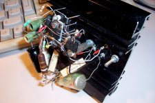
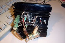
My version is a quick and dirty one (very quick and very dirty), not like KP's "Manhattan". In fact, it is more in the "Favela da Rocinha" urbanistic style than anything else, but after all, electrons don't care too much about this kind of detail.
The results are somewhat disappointing: first, the thing oscillated like mad, and I had to use all the tricks of the book to calm it down: ferrite beads, large gate stoppers, capacitive Zobel, Miller on the phase-splitter MOS.
All of this was just sufficient to keep things under control, but just.
Anyway, this was sufficient to make some evaluations.
First impression without quantitative measurements was good: clean output, no nasties, no offset, etc. Consumption was 2.2A/supply.
I then went a bit further: I had just succeeded in fixing my good old ST1700B, this was the occasion to put it to the test.
With 25Vpp on 4Ω, the THD was 0.02% @1KHz, rising to 0.14% @20KHz.
Not bad, but I had expected better from a class A amplifier.
I also tested the slew-rate: it is heavily asymetrical, with the positive one being only 4V/µs (10V/µs for the negative).
I have used mostly the semi's of the schematic, with the only exception of the IRF510 replaced by IRF610. Probably not very significant, and I had to add a 1nF Miller cap anyway.
Perhaps my method of construction is to blame for the relatively modest performances, but I doubt it. I am used to it, and I know what I have to do to make it work properly, even if the visual result is awful.
I'll post some pics and more details in the following days.
PS:
The version I made is 2i:
http://www.diyaudio.com/forums/solid-state/197707-shunt-regulated-jlh-3.html#post2755344
Last edited:
Perhaps IRF510 .model in LTSpice is overly optimistic?
IRF610 was a completely acceptable substitute. Only
differences maximum voltage and minimum resistance.
So a real MOSFET did not cooperate as well as the sim.
If that's the true case, back to BJTs for those locations...
Messing with other bulletproofings. Schematic starting to
look more like Elvee's shanty town project... But thanks
for report letting me know the stability is wildly suspect.
Your construction was probably not the cause.
I don't know this other way of comping across inputs is
valid? It is bigger cap and lower knee than needed, but
only in effect when there is error uncorrected by the loop.
Stealth comp, I guess? I still put 330p on phase splitter.
The cap on the phase splitter tends to bend distortions
forward, the cap across inputs bends them backwards.
I tried to keep them lined up as the attenuation sets in.
Better transistors on input make a negligible diff. But
maybe again I am letting sim .model overestimate this.
I am for lazy BOM, with few as possible unique parts to
source. BC sumthin sumtin Cwhatever is the reasonable
man's choice, but the BD transistor might also work.
The excessive for this version was to see if I could keep
all the transistors on in severe clipping? The input and
output clipping are helping each other, and neither could
shape an acceptable knee by itself. I still think this is
too many protective parts cluttering up a simple circuit.
-----
2i does not provide enough drive current for 4ohm load
with 2n3055 output devices in the expected droop zone.
R11 R12 would also need to be scaled to that current.
A little surprised it worked with that load. It should be
clipping badly. Maybe you got good batch 2n3055?
Attachments
Last edited:
- Status
- This old topic is closed. If you want to reopen this topic, contact a moderator using the "Report Post" button.
- Home
- Amplifiers
- Solid State
- Shunt Regulated JLH