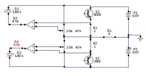
Hi, I was just brainstorming about clipping-indicator and I quickly designed something. Can anybody tell me something like will or won't work? (with the potmeters you can adjust the indicator to the voltage over R1 or R2 at which the amp starts with clipping).
the right values of R3 and R4 must be 1k at 12V supply for the opamps.
greetings,
HB.
the right values of R3 and R4 must be 1k at 12V supply for the opamps.
greetings,
HB.
Attachments
I think hugobross was asking whether his circuit will work, not necessarily looking for other suggestions. However, djk's idea is intriguing. The idea is that under normal conditions the difference between the input and feedback signal will be very small; if the amp is clipping the difference will be larger.
I think hugobross' circuit will work. The top LED is the wrong way around (I haven't checked all the polarities). If you're using a 12V supply for the opamps you may as well connect the LEDs there instead of to 50VDC (saves having a power resistor to drop the LED voltage). You may want to add a bit of positive feedback to the opamps (see references on using comparators) so there is some snap action.
A retriggerable monostable as djk suggests may be necessary to actually see the clipping when it first begins.
so, it might work.
Indeed the top LED is placed incorrectly, the idea is based to compare the voltage over the resistor with the adjusted voltage at the potmeter. When the voltage over the resistor is higher than the "potmeter-voltage" the output will be negative and at max. voltage (in this case -12V) so the led will light up, in the other case the output will be +12V and the led won't light up. Indeed djk, I'll have to connect the leds to the 12V supply, not only to spare power resistors, but also to avoid lighting up the leds with normal use (50V - 12V = 38V so the leds will light).
the right values of R3 and R4 must be 22k
If you must see the led lighting "on time", before clipping, I suggest to adjust a smaller voltage with the potmeter ;-).
I will use this in a self-designed schematic of an amp that I will build soon.
Also thanks for the alternatives, but I try to use and build my own designs, only in this case I can learn as best how schematics work ;-). I use excisting schematics at the moment just to have an idea how other people have realised something, in the future I will try to calculate and design as much on my own (of course with some help of this forum !!).
thanks for the replies,
HB.
hugobross said:Also thanks for the alternatives, but I try to use and build my own designs
Nice sentiment, but every good designer steals shamelessly. Most the commercial products you buy are based at least in part on a reference design from the component manufacturers. Life is too short to do everything yourself. A big part of good engineering is in squezing the best (most, cheapest, smallest, lowest power whatever you are after) from a design. I'm not saying do cookbook designs, but it's a good idea to start with something that works and make it better than it is to spend all your time and money replacing smoked components.
Phil
Phil,
When you really want to design something electronic at your own, you'll have to deal at least once with the blue smoke of burned/exploded components, and the terrible smell of blown capacitors") .
.
That's just the excitement of practically testing your own design:
Is it going to work or isn't it?
HB.
When you really want to design something electronic at your own, you'll have to deal at least once with the blue smoke of burned/exploded components, and the terrible smell of blown capacitors
.That's just the excitement of practically testing your own design:
Is it going to work or isn't it?
HB.
- Status
- This old topic is closed. If you want to reopen this topic, contact a moderator using the "Report Post" button.
- Home
- Amplifiers
- Solid State
- Good clipping indicator?