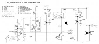
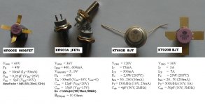
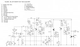
I have assembled and tested another version of the same topology, as presented in this thread. This new version is with BJT active device at the output stage, and the current source is made from three paralleled jFETs. Also, UHF MOSFET was used at the second stage, instead of K117 jFETs.
Using this topology, I was sure, that final sound will be good, and, I was curious in what will be sonic difference, between jFETs and BJTs at the output.
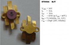
Another side of motivation is that I have got new lots of fancy BJT transistors for UHF applications. One kind of transistors is KT920B (up to 25W collector heat dissipation), it was used in the present version. Another kind of transistors, KT958A, have up to 80W heat dissipation (pins isolated from case), they are to be used in future versions. Apart from good specs, these parts give some additional pleasure, from their yellow-shining view.
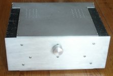
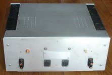
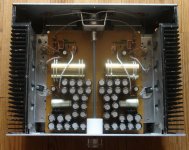
The present version is low-wattage (3…5W) integrated amp, with several audiophile measures taken. Binding posts are Eichmann (gold-plated), volume control pot is Penny&Giles RF15 10K, input wiring is from bulk silver wire in Teflon tubing, output caps are Obbligato Premium Gold 47uF/250V and Nichicon Muse KZ 1000uFx50V. Also attention was given to anti-vibration measured, the PCB is fixed in 16 points, and has downside support in the middle.
Without input R1C1 filter the schematics is very fast, low-signal time shift between output and input sine signals is near 15nsec, but at the maximum volume pot position some ringing is observed on the top of 1MHz square wave signal. This R1C1 makes the situation quiet.
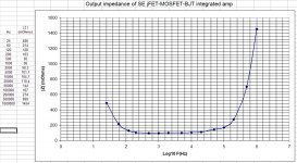
Noise level at the output (max volume) is below 100uV peak-to-peak (thickness of the line at the screen of the scope), complete silence from speakers. Output impedance is 0,1 Ohms.
After the 24h burning-in procedure, some listening comparisons have been done. Compared to jFETs active device version, some very small bass specifics was mentioned (not sure better or worse, a bit more punchy). Highs and Mids are very transparent, difficult to judge about difference with jFETs.
The resulting sound has pluses and minuses for a final user. On the one side, it gives big pleasure from listening of high-quality audiophile recordings. On the other hand, there are not so much high-quality recordings available, and one is forced to mention all imperfections in typical-quality recordings.
Using this topology, I was sure, that final sound will be good, and, I was curious in what will be sonic difference, between jFETs and BJTs at the output.
Another side of motivation is that I have got new lots of fancy BJT transistors for UHF applications. One kind of transistors is KT920B (up to 25W collector heat dissipation), it was used in the present version. Another kind of transistors, KT958A, have up to 80W heat dissipation (pins isolated from case), they are to be used in future versions. Apart from good specs, these parts give some additional pleasure, from their yellow-shining view.
The present version is low-wattage (3…5W) integrated amp, with several audiophile measures taken. Binding posts are Eichmann (gold-plated), volume control pot is Penny&Giles RF15 10K, input wiring is from bulk silver wire in Teflon tubing, output caps are Obbligato Premium Gold 47uF/250V and Nichicon Muse KZ 1000uFx50V. Also attention was given to anti-vibration measured, the PCB is fixed in 16 points, and has downside support in the middle.
Without input R1C1 filter the schematics is very fast, low-signal time shift between output and input sine signals is near 15nsec, but at the maximum volume pot position some ringing is observed on the top of 1MHz square wave signal. This R1C1 makes the situation quiet.
Noise level at the output (max volume) is below 100uV peak-to-peak (thickness of the line at the screen of the scope), complete silence from speakers. Output impedance is 0,1 Ohms.
After the 24h burning-in procedure, some listening comparisons have been done. Compared to jFETs active device version, some very small bass specifics was mentioned (not sure better or worse, a bit more punchy). Highs and Mids are very transparent, difficult to judge about difference with jFETs.
The resulting sound has pluses and minuses for a final user. On the one side, it gives big pleasure from listening of high-quality audiophile recordings. On the other hand, there are not so much high-quality recordings available, and one is forced to mention all imperfections in typical-quality recordings.
Attachments
Last edited:
I expect that it is not difficult to increase output power of this BJT version of the amp.
I plan substitution of VT8-2 KT920B by KT958A, and VT8-1 (the KT602) can be replaced by a medium power transistor with two-three times higher hFE than KT602, like 2SC5694 (hFE=300 is usual for them) or 2SC5707.
Both KT920 and KT958 sure could be substituted by modern parts from NXP or Motorola.
I plan substitution of VT8-2 KT920B by KT958A, and VT8-1 (the KT602) can be replaced by a medium power transistor with two-three times higher hFE than KT602, like 2SC5694 (hFE=300 is usual for them) or 2SC5707.
Both KT920 and KT958 sure could be substituted by modern parts from NXP or Motorola.
Attachments
I would like to ask, possibly this question has already been discussed regarding BJT output stages. What is preferrable, a pair of BJTs with higher hFE, or a triple BJT with lower hFE ?
I have read some objections about using high hFE parts, as they have higher base to emitter resistance. On the other hand, additional part is an additional source of non-linearity. Or current matching to driver stage is the only reason for using triples and quards ? Would be grateful for opinions.
I have read some objections about using high hFE parts, as they have higher base to emitter resistance. On the other hand, additional part is an additional source of non-linearity. Or current matching to driver stage is the only reason for using triples and quards ? Would be grateful for opinions.
I invited a friend of mine for listening comparison of the two amps reported in this thread. He has good experince in installations of systems, both home and professional systems, and good hearing.
Topology of the amps is the same, parts quality and assembling are very similar. Major differences between the amps - transistors used:
1) j103 (jFET) - 2 x K117 (jFETs) - 8 x KP903 (jFETs) - K1529 (current source) Rout=0,6 Ohms
2) j103 (jFET) - KP905 (MOSFET) - KT602-KT920 (BJTs) - 3 x KP903 (current source) Rout=0,1 Ohms
Verdict:
amp 1) has perfect overall tonal balance, very detailed, very pleasant sound, resembles and even outperformes best tubes amps we have happened to listen.
amp 2) has very detailed transparent sound, but one feels very tiny touch of coldness, tonal balance seems to be a bit exaggerated at lows and highs.
Although amp 2) could have some advantages for listening hard rock music, where drive and a shadow of agressivness will not be considered as a minus,
he would definitely prefer amp 1) for home listening.
I conclude, that intrinsic linearity of jFETs compared to BJTs is felt anyway in final sound.
So, one never can repeat by BJTs exact sound from tubes, SITs or jFETs.
Member
Joined 2009
Paid Member
very nice work Vladimirk !
Thanks, Bigun. I am a bit in trouble now, since my previous ideas how to move ahead seem to be not well grounded now.
Maybe, I should try No NFB design, with power UHF BJTs at the output.
Not so good feeling at all. Some years ago, after testing next assembled amp, I always had reasons for unsatisfaction and further motion.
I conclude said:You do know that this statement is totally wrong, I hope. Bjt s are more linear than Jfets when degenerated for the same transconductance. This is the only way comparisons can be made.
This has been proven and every qualified engineer in the world knows this and has done lab testing proving this when he takes the course at university.
Hundreds of books would have to be destroyed, highly educated professors and doctorates rediculed and electronic history rewriten in case youre correct which youre not.
That they do sound different, yes, there are many that prefer BJTs but it has nothing to do with linearity.
Vladimir,
You are now up against the psychoacoustic dimension - the precise way in which humans perceive sound and the distortions introduced by electronic and mechanical reproduction.
This is subjective. There is no definitive answer. Some like it sweet, some sour, and some savoury.
Alex is correct, although he is rather harsh.
Hugh
Member
Joined 2009
Paid Member
Thanks, Bigun. I am a bit in trouble now, since my previous ideas how to move ahead seem to be not well grounded now.
Maybe, I should try No NFB design, with power UHF BJTs at the output.
Not so good feeling at all. Some years ago, after testing next assembled amp, I always had reasons for unsatisfaction and further motion.
Going in the no NFB direction would be worth exploring. The tube amps you compare with are usually no NFB aren't they ?
I think use of NFB has a significant impact on the design and implementation of an amplifier - it changes the interaction of the amplifier with the load in a fundamental way.
I'm not saying NFB is bad, I'm saying that using it or not using it is a decision at the foundation of the amplifier.
I think use of NFB has a significant impact on the design and implementation of an amplifier - it changes the interaction of the amplifier with the load in a fundamental way.
I do agree completely with this your statement, I would add also that basic topology of an amp is more important for interaction with the load than the measured Rout. And in this respect, NFB of current type gives definite advantages.
I assembled and did listening comparisons of several No NFB designs, with RF MOSFETs at the output. Although they were very good overall, I felt some touch of imperfections at low frequencies.
I did not believe that NFB design could sound as presize as those No NFB amps, but the schematics at the beginning of this topic has surprised me, it gave the same perfection at mids and highs, but at bass it was unexpectedly perfect, in spite of 0,6 Ohms Rout (No NFB designs had 0,2 Ohms Rout). Since the same NFB topology with BJTs at output gave something a bit different, I find it logical to try No NBF with jFET input, BJTs emitter follower output . If even in this case one could find a flavour of BJTs, than ... it will be evident, that there is something intrinsic to BJTs, in spite of how are they used, with what degree of degeneration. At this, I would like to add, that this story goes about quite a tiny sound perception effects, that can not be important for a majority of listeners, and that can hardly be explained proceeding from extensive academic knowledges. I speak hear mostly about research interest and satisfaction of curiousity, about sound aspects that could be sensed with rather high level system. Yes, about subjective aspects of sound perception, expressed by a completely unbiased persons with good experience in listenings and with good hearing.
I would also pay attention to the fact, that Yamaha B1 and B2 amps sound in their specific (preferred by almost everybody) manner, due to mainly the fact that SIT transistors stand at their output. Who precludes to put degenerated BJTs there, is one sure that the same sound signature will be achieved? By the way, I listened at my system Yamaha B2x, the model next to B2. In this B2x BJTs were used instead of SITs. What can I state, the B2x does have a touch of agressiveness at highs.
Last edited:
Here is another version of this schematics topology, it provides more power and still similar perfect sound. T2 could be replaced by 2SK215 (with decreasing R3), and T3 could be simply a resistor. T10 could be some other current source, based on MOSFETs or BJTs.
T2 and T3 must be close to each other, mounted on the same heatsink.
Output impedance modulus 15 mOhms (1kHz). At frequencies below 100Hz, impedance has a capacitive character, above 50kHz - inductive. Output power - 20W at 8 Ohms, 10W at 4 Ohms. Important resistors R5 and R6 - Kiwame carbon composition 5W.
Attachments

Last edited:
Member
Joined 2009
Paid Member
are there any updates on your experiments Vladimirk - or did you find the sound too good to move on to new designs")
Hello, Bigun
Yes, there were some updates. In the post's 1 schematics, I have replaced the paralleled 8-jFET active device by simple triple darlington with powerful bjt VHF transistor (300MHz 300W) at the output. It is russian KT980A transistor for radio applications. This is a version that I enjoy most of all, the bottom end has improved compared to 8-jFET version. At the same time, I can not notice any "transistor" sound artefacts, no any GNFB atrefacts, even mids and highs are the same or better than from 300B SE tube amp. With 8-jFET I had a sound that is very close to the tube amp.
Also I tested some NoGNFB schematics and concluded, that fast powerful Ge bjt transistors are welcomed to the output in such topologies.
No I am completing an integrated amp with 1T910A Ge output transistors (30MHz 35W). 30MHz is OK for NoGNFB design. In this design I use a differential stage driver, based on KP903B jFETs, tail current is 100mA, drain load resistors are 330 Ohms, source resistors 8 Ohms, voltage amplification is 6,3, decently reproduces 1MHz square wave.
Last edited:
- Status
- This old topic is closed. If you want to reopen this topic, contact a moderator using the "Report Post" button.
- Home
- Amplifiers
- Solid State
- jFET amp with current NFB