The more sophisticated the electric circuit, the less reliable the product will be.
After years of experience in the Audio field, I can say with certainty that despite all the protection of any kind, I steel have fix amplifiers. The protection works until ...? the damage was done. and it done.
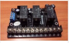
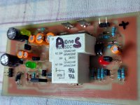
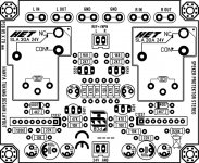
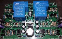
The most functional protection circuit for preventing damage is preventing DC to the speakers. I have many examples that i made for 2,4,6,8,13 channels
After years of experience in the Audio field, I can say with certainty that despite all the protection of any kind, I steel have fix amplifiers. The protection works until ...? the damage was done. and it done.
The most functional protection circuit for preventing damage is preventing DC to the speakers. I have many examples that i made for 2,4,6,8,13 channels
Attachments
Hi Terry,
for the OCP, it has you sensing the voltage across the top side emitter resistor, so sensitivity depends on the emitter R size.
they should have used 2 more resistors, allowing you to form an attenuator, (R across the 2u2) so you can change the sensitivity, but you can add that if needed.
Good luck
for the OCP, it has you sensing the voltage across the top side emitter resistor, so sensitivity depends on the emitter R size.
they should have used 2 more resistors, allowing you to form an attenuator, (R across the 2u2) so you can change the sensitivity, but you can add that if needed.
Good luck
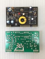
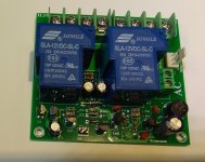
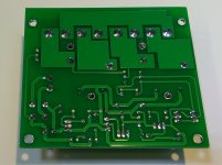
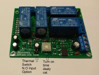
Over current and dc protection
Ho andrewlebon, can you share this pcb?
Hello Thimios
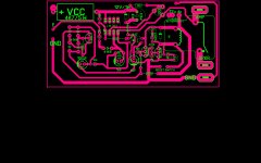
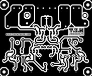
greetings just give me few days for proper pcb design.
warm regards
Andrew;
Ok thanks!
Fuses suck. They blow right after the amplifier fails. How about don't fool with the wires while it's running? After I blew up enough amps I decided not to mess with the wiring while it's playing and haven't had an issue in over 30 years.
G²
It depends on where you put the fuse. If you put a fuse in serial with the each output transistor's collector. It is pretty sure to blow before your amplifier fails.
If the fuse is located on the power supply transformer primary (even on secondary) side. Just as you said, they blow right after the amplifier fails.
I have searched this thread and didn't find it. But there is a nice solution for current limit / short circuit protection together with bias current regulation by use of Analog Devices LT1166.
https://www.analog.com/media/en/technical-documentation/data-sheets/1166fa.pdf .
A hint from me, the circuit design can be made much simpler as shown in the data sheet. You can build it up just with the LT1166, the 2 emitter / source resistors and a 15 mA current regulation diode. If someone is interested I can submit the circuit design.
Last edited:
- Home
- Amplifiers
- Solid State
- diy short circuit protection