Hi
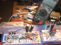
Recently my job activities has been at minimum, at least for the last couple months so I have not been able to procure the funds to continue with my balanced amp project. Since I disassembled the prototype I realized I needed some tunes in my 'construction room'. So I got out a pencil and paper and started thinking of a simple amp I can make on a breadboard, with old parts I have laying around in the junk bin, just to use. We all have junk parts boxes and I'm sure some of you have some really nice components in them. Anyway, to alleviate my current boredom, this little amp is what my mind regurgitated, after a bit of experimentation of course.") Turns out, to my surprise, it works really damn good! So I figured I'd share it with y'all.
Turns out, to my surprise, it works really damn good! So I figured I'd share it with y'all.
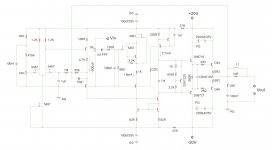
It is a 'one transistor' input stage. The input voltage signal is translated to a current signal. This signal is then summed with the signal current from the DC servo and feedback loop at the Wilson mirror via the dependent current sources (the collectors) of two common base amplifers. The mirror is the VAS with a CCS load. The drivers are 2N6716/6727 from Central Semi, the ones in the TO-237 package, TO-92 with a tab. The OPS is a simple complementary class AB bias EF stage. If my boredom persists I may have to adapt a HEC vertical mosfet OPS. I could drive half the load Z with the same size TO-220 transistors. But for now this works fine and is much less complicated. All the BJT’s that are not labeled could just as well be 2N3904/3906 types. I found a set of outputs in the part box, D44/D45, but the D44 was shorted. Oh well, I found a MJE3055 laying in there as well so used it instead. The datasheets appear to be similar and it works fine here. I didn't have to buy anything for this circuit.
I can set DC to zero volts and it only varies a few mV. Now if I were to go out of my way to measure and match J-fet Vgs to the mV there would be no need for the 10K pot, 470K, 33K, 100nf cap at the left side of the drawing and DC offset would be perfect.
So anyway, feel free to play with it and evaluate.

Recently my job activities has been at minimum, at least for the last couple months so I have not been able to procure the funds to continue with my balanced amp project. Since I disassembled the prototype I realized I needed some tunes in my 'construction room'. So I got out a pencil and paper and started thinking of a simple amp I can make on a breadboard, with old parts I have laying around in the junk bin, just to use. We all have junk parts boxes and I'm sure some of you have some really nice components in them. Anyway, to alleviate my current boredom, this little amp is what my mind regurgitated, after a bit of experimentation of course.
Turns out, to my surprise, it works really damn good! So I figured I'd share it with y'all. It is a 'one transistor' input stage. The input voltage signal is translated to a current signal. This signal is then summed with the signal current from the DC servo and feedback loop at the Wilson mirror via the dependent current sources (the collectors) of two common base amplifers. The mirror is the VAS with a CCS load. The drivers are 2N6716/6727 from Central Semi, the ones in the TO-237 package, TO-92 with a tab. The OPS is a simple complementary class AB bias EF stage. If my boredom persists I may have to adapt a HEC vertical mosfet OPS. I could drive half the load Z with the same size TO-220 transistors.
But for now this works fine and is much less complicated. All the BJT’s that are not labeled could just as well be 2N3904/3906 types. I found a set of outputs in the part box, D44/D45, but the D44 was shorted. Oh well, I found a MJE3055 laying in there as well so used it instead. The datasheets appear to be similar and it works fine here. I didn't have to buy anything for this circuit.I can set DC to zero volts and it only varies a few mV. Now if I were to go out of my way to measure and match J-fet Vgs to the mV there would be no need for the 10K pot, 470K, 33K, 100nf cap at the left side of the drawing and DC offset would be perfect.
So anyway, feel free to play with it and evaluate.
Attachments
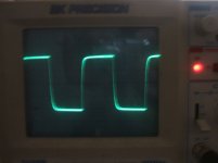
This 10Vp, 10KHZ square wave shows this simple amp is not nearly as fast as my bridge amp but I suppose it will suffice as a 'temp amp'. I added some voltage measurements at the input stage.
One thing is for sure this circuit is it is very stable. Lots of folks here search for a novice circuit that works well and is easy to construct. I've made the typical LINs back when I first started into the hobby and I have to admit I feel ignorant for not coming up with something like this before.

I bet with some improvements such as cascode of the mirror and CCS, a more capable output stage, it could have real potential. It might be worth pondering over a bit more. I may do so this weekend, if there is any interest I will post what I come up with.

I added some voltage measurements at the input stage. One thing is for sure this circuit is it is very stable. Lots of folks here search for a novice circuit that works well and is easy to construct. I've made the typical LINs back when I first started into the hobby and I have to admit I feel ignorant for not coming up with something like this before.
I bet with some improvements such as cascode of the mirror and CCS, a more capable output stage, it could have real potential. It might be worth pondering over a bit more. I may do so this weekend, if there is any interest I will post what I come up with.
Attachments
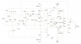
The FET input stage is mostly for the simplicity of the -Vgs to set the input stage bias. Also the FET/BJT arrangement allows for very little current change in the FET, just the change in base current, so there is very little variance in Vgs. This is important since these devices are not within a feedback loop. I've discovered the arrangement to be very applicable.
- Status
- This old topic is closed. If you want to reopen this topic, contact a moderator using the "Report Post" button.