Hi,
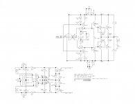
I am going to build hybrid amplifier. I want to use 100W output stage from Krill amplifier. I have several questions about the output stage.
First, how should I modify the input of the output stage to make it work with external preamp and what is the input impedance of output stage?
Second, can I substitute drivers from 2SC5200 to MJ150030?
Third, can I substitute signal transistors to BD139 and BD140 - propably worse sound, but I already have them.
Thank you.
Attachments
Hi,
I am going to build hybrid amplifier. I want to use 100W output stage from Krill amplifier. I have several questions about the output stage.
First, how should I modify the input of the output stage to make it work with external preamp and what is the input impedance of output stage?
Second, can I substitute drivers from 2SC5200 to MJ150030?
Third, can I substitute signal transistors to BD139 and BD140 - propably worse sound, but I already have them.
Thank you.
Are you saying you want to substitute a tube VGS for the VGS shown in your attached schematic?
The output stage will accept almost any transistor that meets the power and voltage requirements.
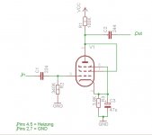
I tried a Tube vgs : http://www.diyaudio.com/forums/soli...ction-thread-100w-version-40.html#post2266198
Not 100W but sounds very good.
Not 100W but sounds very good.
I am curious how it will sound with aikido preamp. I too will not have 100W output power, because I will have lower voltage rails (30V), but want to use double output pairs to lower output impedance.
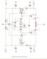
But how to modify the input transistors? Should I connect 1k in series and 47k to ground resistor from base of input transistors?
But how to modify the input transistors? Should I connect 1k in series and 47k to ground resistor from base of input transistors?
i just used two resistors to trim the base of Q7/Q10. One resistor was 680K, other one 1Meg Pot.
Tube is EF86 in Triode Connection. V=200V. All Values of Restistors and Caps are rough guesses ...")
Edit: Attachments
Tube is EF86 in Triode Connection. V=200V. All Values of Restistors and Caps are rough guesses ...
Edit: Attachments
Attachments
Last edited:
Member
Joined 2009
Paid Member
You can probably get rid of one of the capacitors in the signal path - either the input cap or the inter-stage cap through a judicious choice of power rails for the tube.
Steve - correct me if I'm wrong - but I also believe you'll benefit if you can afford to add more output transistors. With no gnf the output will tend to have more distortion and lower damping factor than with gnf. Additional output devices will help you reduce the output impedance, they will also have less current variation through each one so lower distortion. And as far as I can see, the Krill output stage benefits even more from additional devices because more devices means more base-storage of minority carriers which is what is behind the distinctive non-switching / soft-switching characteristic.
Steve - correct me if I'm wrong - but I also believe you'll benefit if you can afford to add more output transistors. With no gnf the output will tend to have more distortion and lower damping factor than with gnf. Additional output devices will help you reduce the output impedance, they will also have less current variation through each one so lower distortion. And as far as I can see, the Krill output stage benefits even more from additional devices because more devices means more base-storage of minority carriers which is what is behind the distinctive non-switching / soft-switching characteristic.
i just used two resistors to trim the base of Q7/Q10. One resistor was 680K, other one 1Meg Pot.
Tube is EF86 in Triode Connection. V=200V. All Values of Restistors and Caps are rough guesses ...
Edit: Attachments
With a cap coupled input you must use something like this. I used one 1 MEG 10 turn pot from each power supply rail to the base of Q7/Q8. That leaves the input impedance at something over 400 K ohm.
You can probably get rid of one of the capacitors in the signal path - either the input cap or the inter-stage cap through a judicious choice of power rails for the tube.
Steve - correct me if I'm wrong - but I also believe you'll benefit if you can afford to add more output transistors. With no gnf the output will tend to have more distortion and lower damping factor than with gnf. Additional output devices will help you reduce the output impedance, they will also have less current variation through each one so lower distortion. And as far as I can see, the Krill output stage benefits even more from additional devices because more devices means more base-storage of minority carriers which is what is behind the distinctive non-switching / soft-switching characteristic.
That is basically correct. The actual bias current has some effect on the output impedance also.
- Status
- This old topic is closed. If you want to reopen this topic, contact a moderator using the "Report Post" button.
- Home
- Amplifiers
- Solid State
- Krill output stage + tube preamp