Hi,
well, we are near...switch-on.
Kiwi & NicMac...please,confirm package.
@Arthur: caps 1206 arrived today.
Still waiting, package should arrive tomorrow
Will let know asap.
AndrewT is back. I have been away on extended holiday.............. that Andrew T has given up DIY, he doesn't seem to have posted anywhere for weeks
Starting to catch up with the post and the Email and the DIYaudio.
Got my first build playing music for about 6hrs yesterday.
It did not blow up. The noise performance is not brilliant, it does not measure <0.1mVac, it varies from 0.1mVac to 0.2mVac, the tiny oscillation I reported is still there.
I have almost finished the second build. I will test it and then repeat testing with the 0r0 for R54, instead of the 10r I used in build one.
Build one has a tiny bit of hum audible at the speaker, but inaudible at the listening seat. That hum will be the poor noise that I measured. And could be caused by "my 10r" for r54.
More when I get build two finished.
I have been studying the PCB to see what the input traces do.
I see three connections on the schematic for "OUT 1".
I can find two PCB traces connected to PIN8 (going to R43 and then on to R48). The third trace appears to stop at at plated through hole that is not connected on the reverse side. I cannot see a connection from SPKR + to the feedback path @ pin8.
Similarly, I cannot see a connection to the second side of the mute switch pair.
Can OPC, or anybody, show where these "connections" have gone?
Are the INPUT labels + & - swapped?
Hi,
well, we are near...switch-on.
Kiwi & NicMac...please,confirm package.
@Arthur: caps 1206 arrived today.
Package received, thanks Roberto!
wb Margus
AndrewT is back...
I have been studying the PCB to see what the input traces do.
I see three connections on the schematic for "OUT 1".
I can find two PCB traces connected to PIN8 (going to R43 and then on to R48). The third trace appears to stop at at plated through hole that is not connected on the reverse side. I cannot see a connection from SPKR + to the feedback path @ pin8.
Similarly, I cannot see a connection to the second side of the mute switch pair.
Can OPC, or anybody, show where these "connections" have gone?
Are the INPUT labels + & - swapped?
Hi AndrewT, hope your vacation was enjoyable
")
Gotta remember the pcb is more than 2 layers, so there will be a few traces hidden away in the center layer... I can visibly see two traces from pin 8, one connecting to R39 (bottom layer), the other running toward SPKR+ (mid Layer) & can see a mid layer trace coming from SPKR+. From -input you should be able to follow the traces through C76 to R43, a Via to R39, R39 connects to Pin 5 & Pin 8, Pin 8 connects to SPKR+...
R48 is the OR jumper on the +input, so shouldn't be connected to the feedback path in any way...
If you backlight the pcb it makes it easier to see some of the mid-layer traces...
Paul.
Last edited:
Thanks BMS, I can see a buried "something" emanating from SPKR+ towards the middle of the PCB. Yes, R39&Pin8 have continuity to SPKR+.
Yes, Mute switch has continuity to Pin2.
That extra layer/s confirms where the "allegedly missing" connections have gone.
From post1
Yes, Mute switch has continuity to Pin2.
That extra layer/s confirms where the "allegedly missing" connections have gone.
From post1
The PCB will be a 3 layer design
Hello, you're still in the sea?
no heard a DPS-600 with Wire-Amp?
I have some new info.
Since the DPS-500 has a power unit very expensive, I thought that it is possible to mount the same power unit of the DPS-600 (do not need to make changes), so the difference is in the use 115VAC/230VAC with a small increase power, thanks to the cell filtering slightly larger.
This allows me to offer the DPS-500-WA with only +15 € difference.
Obvious that the original version is available (such as those that I'm sending to Owen for the test and measurement).
That's all for now.
I know well that the monetary crisis has spread out from Europe, so is not easy, spending money on unimportant things.
but if someone needs a good power supply for audio,with new performances on audio transient, this is the right one
Regards
Roberto
Attachments
Last edited:
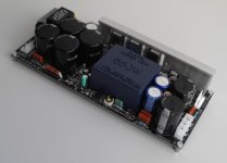
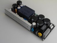
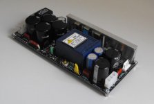
Original version "S" for WA.
This version can supply up to two amps (if AB class) up to 2x300W rms or
2x500w in case of D Class.
however, can provide repetitive peak power (33/66ms) of 1kw without fan.
sag voltage is around 2.7-3V, also (this power supply have two feedback) to get a very fast reset time. (load on one rail, not unbalanced the other side).
--------------------------------------------
right for clarity. than the version not "S", changes the transformer and all components within the Power-Unit. the electronic circuit is identical
regards
Attachments
Last edited:
I'm officially throwing in the towel on this project. If anyone is interested in 2 pairs of never-soldered MOSFETs and 2 unused PCBs (well, I think I have two...though I can't find one at the moment), please let me know.
I have one nearly-completed board (except for MOSFETs) that I would be willing to sell too, but of course, no warranty!
PM me for inquiries.
I have one nearly-completed board (except for MOSFETs) that I would be willing to sell too, but of course, no warranty!
PM me for inquiries.
AP2:
If you'd like to send me the pair of new supplies, I'd be happy to test them. I got a UPS shipping notification from you but the items were never dropped off.
I would really be keen to test something with a 110-120VAC input as it might provide a viable option for other North American builders in this thread.
FloridaBear:
I'm sorry to hear you've given up on these! Can I ask why you've decided to throw in the towel? Perhaps it's something people on here can help with.
This is by far the most advanced project I've offered, and requires some level of implementation skill on the part of the end user, but it should be possible to get the amplifiers up and running without too much trouble.
If there's something in particular that is holding you back, let us know and maybe we can offer some support.
Cheers,
Owen
Hi all,
Some info about WE-smps.
from GB,i have available 4xDPS-600/55 +one /45.
Other new's is DPS-400+PBTU-2 kit (possible big discount on it)
this smps play very quiet and is indestructible, (2x) is very nice for dual mono amps.
well, we wait new measure from Owen on DPS-500/S.
Regards
Some info about WE-smps.
from GB,i have available 4xDPS-600/55 +one /45.
Other new's is DPS-400+PBTU-2 kit (possible big discount on it)
this smps play very quiet and is indestructible, (2x) is very nice for dual mono amps.
well, we wait new measure from Owen on DPS-500/S.
Regards
FloridaBear:
I'm sorry to hear you've given up on these! Can I ask why you've decided to throw in the towel? Perhaps it's something people on here can help with.
This is by far the most advanced project I've offered, and requires some level of implementation skill on the part of the end user, but it should be possible to get the amplifiers up and running without too much trouble.
If there's something in particular that is holding you back, let us know and maybe we can offer some support.
Cheers,
Owen
It's actually several things, but perhaps it boils down to lack of motivation to finish. I suppose the main issue is that the SMD parts were just beyond my skill (and/or patience) level. At least now I know my limits!
LME49830 + Lateral MOSFETs
Owen (OPC): FYI, nice project!!
I am inspired & have sort of copied your design for my own project PCB. You are not offering PCBs anymore, so I have to brew my own. I do not mind, lots of fun designing a new winter project.
I read that Andrew T. has commented, that the HS for the LME gets really hot, (to touch) when the supply gets up high. I am wondering if I will be required to use a larger HS, any comments? heat = enemy, for long term reliability!!
I calculate the LME PwrDiss (no-signal) at around, 150V*25mA = 3.75W
I have managed to buy ($20) a used transformer on eBay, from a parted Pioneer SX-1250, hope it works okay.
The Pioneer xformer has many separate windings, I will use one set for the regulated supply to the LME. Will also put out ~ +/-75V unregulated & has 2 separate windings for the regulated for each channel, unloaded ~ +/-70V.
I will post the layout in a new thread, once I get it in reviewable condition. Hopefully you and some of the other experts can review and provide me with some feedback.
BTW, how did you generate the schematic with the pop-up part descriptions, really cool, does your CAD SW do this for you? & who's CAD SW do you use, let me guess RIM = Mentor Graphics. I meet some RIM CAD folks at a MentorG seminar once apon a time.
P.S. Take care & Happy Thansgiving for us Canucks
SMT soldering HELP!!
If I was around the corner from you, I'd solder those few SMT parts for you. Actually not as difficult as it seems. The SMT parts must be solder first or you will have problems because of interference from the large PHT parts that will interfere. A small tip on the soldering iron is important. A small jewlers maginifier 10x goes a long way for inspection. Twezzer capable of picking up small 0805 SMT parts is required. Add a small amount of solder to one pad, place/centre the part on top, solder the part/pad where you added the small amount of solder, then sloder the other side. Using small diameter ~0.020", solder helps alot, as you can control how much solder that you apply. Piece of cake even for an ole fart like me!!
Good Luck
Rick
It's actually several things, but perhaps it boils down to lack of motivation to finish. I suppose the main issue is that the SMD parts were just beyond my skill (and/or patience) level. At least now I know my limits!
If I was around the corner from you, I'd solder those few SMT parts for you. Actually not as difficult as it seems. The SMT parts must be solder first or you will have problems because of interference from the large PHT parts that will interfere. A small tip on the soldering iron is important. A small jewlers maginifier 10x goes a long way for inspection. Twezzer capable of picking up small 0805 SMT parts is required. Add a small amount of solder to one pad, place/centre the part on top, solder the part/pad where you added the small amount of solder, then sloder the other side. Using small diameter ~0.020", solder helps alot, as you can control how much solder that you apply. Piece of cake
even for an ole fart like me!!Good Luck
Rick
If I was around the corner from you, I'd solder those few SMT parts for you. Actually not as difficult as it seems. The SMT parts must be solder first or you will have problems because of interference from the large PHT parts that will interfere. A small tip on the soldering iron is important. A small jewlers maginifier 10x goes a long way for inspection. Twezzer capable of picking up small 0805 SMT parts is required. Add a small amount of solder to one pad, place/centre the part on top, solder the part/pad where you added the small amount of solder, then sloder the other side. Using small diameter ~0.020", solder helps alot, as you can control how much solder that you apply. Piece of cake
Good Luck
Rick
completely disagree with underlined part, in fact i'd almost bet money that having too little mass in his tip is the main problem here. this amp has very solid ground planes and they suck the heat out of small tips, you wont get anywhere. a 3mm chisel tip is perfect for doing everything on this board
if I was nearby I would help also, but that sure isnt the case.
Hello "qusp" I have no problem with smaller tips on my irons, just have to turn the temperature up to around 700-750F. If your iron does not have temperature control or enough heat/wattage then yes a small tip can be a problem where a full contact pad to a copper plane will pose an issue. I was just trying to help the person out, so much for trying. BTW, I have years of experience soldering SMT parts, I am not an amateur at this!!
- Home
- Amplifiers
- Solid State
- "The Wire AMP" Class A/AB Power Amplifier based on the LME49830 with Lateral Mosfets