This is the way the Summer/Winter setting of one of the Krell Klones was done.would it be better to have it so that 2 identical resistors were used, one in circuit all the time and another switched in in parallel? I presume lower resistance = higher current? this way there is never a time, no matter how short where there is an open circuit this way it could easily be 300 and 600ma, or calculate 200 and 600 easily enough
The way i understood it the PBTU-2 was used for the DPS400 measurements. And it is just a few large capacitors in the high power rail and two LME317/337 regulators + caps for the low power rail. There is a schematic in the datasheet.
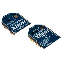
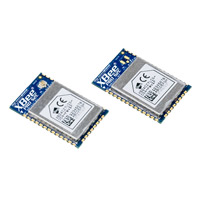
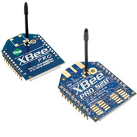
I stated this to try to make it clear, but I still think you are misunderstanding. the remote switch is a mechanism to effect the control of a resistor, just a standard resistor, not actually BE the resistor. we are not talking about a digital resistor, simply a control voltage that can trigger another mechanism like a relay or some other type of resistance. specifically in my case i'm talking about using one of the control channels of an xBee, digimesh, if we spin a PCB as i'd like to, we could include a relay, the 2 resistors and a zigbee embedded SMT version, which would allow the use of internal or small external aerial connected with u.fl on the rear of the components . which has self discovery and self healing, so will act on its own to re-establish a connection with the group when disconnected; as well as being low power (1mW) to keep chances of induced oscillation as low as we can, wifi operates at 2.4GHz anyway so thats pretty unlikely.Regarding the bias adjust, to add a switch resistor in parallel sounds like a better idea. The relay can either connect or disconnect the second resistor. But wouldn't a digitally adjustable resistor cause less risk for transients during the change? Sure this increases complexity a lot.
But if the microcontroller is used it can also be made to handle mute on startup and shutdown by making something to detect the mains connection.
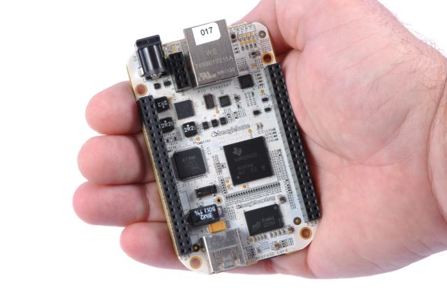
The idea being that this will be part of a network of this type of module placed in this amp, my dac, the LPUHP and their power supplies. controlled and monitored with a beaglebone based central MCU. we will have one of these in the amp anyway for monitoring and sequenced start/shutdown of the whole system.
yes and no i'm not sure why you are worried about a transient if its done properly; even if that just means using a make before break. I think the parallel resistor setup will probably be best.Is there a simple and effective way to connect/disconnect the amp from the supply during startup/shutdown assuming that a microcontroller is available? Relay is one option but i'm a bit worried about creating a transient when you just break the current.
Hey thanks Andrew, glad its been used before successfully; seems to be the best way forward for start up, just need to work on shutdown
there are all manner of dacs with multiple outputs commercially, decent soundcards, diy there is a couple of AKMs, the sabre, a wolfson or 2 and few crystal semi chips. otherwise its a simple enough manner to feed more than one stereo dac. cheapest option is the soundcards. its a bit of a myth that you cant hear direction of bass, 2 subs is better, but how were you planning to combine or are you using a commercial active sub? the wire seems a bit overkill for computer speakersMy current plan about the usage is to get a 2.1 system for my computer since i guess that the smaller speakers that fit on the desk cannot handle the low frequencies hence the woofer. I assumed that in a stereo dac the complete audio signal is present so i can just take the low frequency content from the left/right channel to the sub. I think this should work decently because you cant hear the direction from the low frequency response.
I have seen extremely few dacs with more than two outputs.
Last edited:
the wire seems a bit overkill for computer speakers
Don't insult "computer speakers"
 I will use 150+WRMS/8ohm for XTZ 93.23
 Audio Power SMPS GB
Emphrygian x 2- DPS600 - around +/-60V
igor0203 x 2 - DPS600 - +/-65/55V
qusp x 2 - DPS600 - +/-55V +/-5%
lolo x 10? DPS600 - +/-?? (fill in)
??
Total 16 x DPS600
yes remote start up seems pretty straight forward and catered for already, just a clean way to increase the bias after 10-15 seconds is needed. is there some sort of 'i'm ready and stable' signal that we can hijack, or we must just use a timer, or rail voltage sense?
i'm not sure about getting rid of the linear reg, there is no way to mount the DPS600 as close as the regs that most of us already have in our kits; unless there is a decent saving, I think I would prefer to have the supply as is so it can be easily used in other projects if need be. not sure on that i'll need to think about it. it would also mean that the PSU is sharing my heatsinks and TBH i'd prefer if it was autonomous in that regard; it places restrictions on mounting and chassis format as well. What do others think?
is there some way to have ring terminals instead of that molex type connector? i'm not a big fan of these for high current, but i'll live.
Emphrygian x 2- DPS600 - around +/-60V
igor0203 x 2 - DPS600 - +/-65/55V
qusp x 2 - DPS600 - +/-55V +/-5%
lolo x 10? DPS600 - +/-?? (fill in)
??
Total 16 x DPS600
Hi all,
well, I'm just finishing some work, next week I devote some time to fix some things and adapt it better to amp wire.
considered that the DPS-600 has a simple remote control with 2 pins (including LED) and measure of Owen ref to AC cable unplugged.
option for the voltage, it is preferable to find the lowest, i think 55-60V DC for power DC.
Also, decide if the DPS-600 must have the regulators on board for lme or not. (i advice yes) then requires no external parts.
Another detail (need a photo for this) is better than DPS-600 does not include the bottom panel (apart reduces cost). I think that will be mounted on a metal base of case, in vertical or horizontal. (heatsink includes aluminum adapter). ready for screw.
yes remote start up seems pretty straight forward and catered for already, just a clean way to increase the bias after 10-15 seconds is needed. is there some sort of 'i'm ready and stable' signal that we can hijack, or we must just use a timer, or rail voltage sense?
i'm not sure about getting rid of the linear reg, there is no way to mount the DPS600 as close as the regs that most of us already have in our kits; unless there is a decent saving, I think I would prefer to have the supply as is so it can be easily used in other projects if need be. not sure on that i'll need to think about it. it would also mean that the PSU is sharing my heatsinks and TBH i'd prefer if it was autonomous in that regard; it places restrictions on mounting and chassis format as well. What do others think?
is there some way to have ring terminals instead of that molex type connector? i'm not a big fan of these for high current, but i'll live.
no problem, i'll do what I can there, I can help out some with organizing as my responsibilities for the LPUHP GB are not far off finished. as long as I dont have to receive and distribute i'm OK to help out, but just with logistics and rounding everyone up for payment, we should arrange for the units to be shipped directly to the owners though, its really the only way that makes sense, otherwise there would be more tax and extra insured shipping legs/repacking quoting everyone's shipping, customs, responsibility etc. that scenario I would not have the time, nor desire to doOne problem is, that i can not follow well group list, then need someone.
yeah well with the measures out there so thoroughly, there would have to be a pretty big magical hole/parallel world to be anything other than a fantastic combination.One last thing, that this amplifier performances in conjunction with this special SMPS, in relation to the definition of musical timbre and attack speed (in the dynamic nature of some musical instruments) or sustain orchestral performances is beyond the typical audiophile amplifier with 30Kg .
I say this only because it is a truth that can not be hidden.
Regards
Last edited:
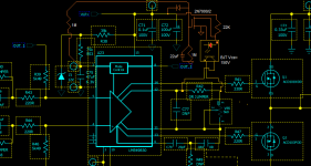
Other possible way (simple) without relay.
for bias switch.
Also in this scheme, you can add a photo diode (in series at the drain) to control the external bias.
this detect only on "time" when ready.
Obvius that can use comparator for detect voltage rail but i know that pcb is already printed,then think a simple external modify.
for bias switch.
Also in this scheme, you can add a photo diode (in series at the drain) to control the external bias.
this detect only on "time" when ready.
Obvius that can use comparator for detect voltage rail but i know that pcb is already printed,then think a simple external modify.
Attachments
aaahh yes, but its the inverted commas in 'computer speakers' that make all the difference =) i'll be running fairly nearfield 'computer speakers' tooDon't insult "computer speakers"

but
this seems a little different does it not? ,maybe I have assumed too much, but this sounds dinky/littleMy current plan about the usage is to get a 2.1 system for my computer since i guess that the smaller speakers that fit on the desk cannot handle the low frequencies hence the woofer.
nothing wrong with computer as source; I happen to think its where the best sound is coming from these days.
@ Roberto: i'll have a look at both your schematics in the morning, I find it a bit difficult to read this diagramatical style, it will be easier if I print it out. sounds about right, I want all this stuff monitored anyway by the MCU,so its not a big deal I dont think, to extend that to an active feedback system
Last edited:
Hi Guys,
Sounds like the first kits are starting to arrive, and I'm excited to see some of these starting to come to life!
I have a few comments about the last few pages:
1. Th PBTU is simply a capacitor bank for the LV rails, and a simple linear reg section with a few more caps for the HV rails. It's a pretty clean little "go between" that I would strongly recommend with the DPS-400. All measurements of the DPS-400 were performed with the PBTU in place. The DPS 600 does not use the PBTU, and all those measurements were done without it.
2. The DPS600 I tested with did not have the HV regulators in place. I would strongly suggest having them as it's a good way to adjust the HV levels, and it should provide somewhat lower noise.
3. With the above, my separate reg board will probably not be needed, but might work well if used right near the amp itself. Either way, I'm sure people who ordered the PSU kit and want to buy the DPS-600 will be able to find another use for a good small +/-15V supply. I personally have about 8 of them in service right now, powering a variety of other gear, including the analog sections of my Behringer DCX.
4. For the bias adjust, I should have been a little more clear. You definitely want the relay to put another resistor in parallel with the existing one to change bias levels. You do not want to change between two different resistors as the amp could behave very poorly if you do this. You can also add a capacitor across the main resistor to slow the change in the bias setpoint.
Regards,
Owen
Audio Power SMPS GB
Emphrygian x 2- DPS600 - around +/-60V
igor0203 x 2 - DPS600 - +/-65/55V
qusp x 2 - DPS600 - +/-55V +/-5%
lolo x 10? DPS600 - +/-?? (fill in)
QRikard x 2 DPS600 - +/-45V (55V works as well)
??
Total 18 x DPS600
. The XTZ 93.23 looks nice i plan to get something similar so it wont be those tiny plastic things you find at the local supermarket...
I have started more and more to look at multichannel solutions, but the nice looking solutions i have found is usually in a different pricerange and my money is running short so the most likely solution is to wait and save up some money.
Another reason for 2.0 dac is the ODAC from NwAvGuy, looks promising and should hopefully be fairly cheap and good performing when it's released...
I did misunderstand the full concept you were going for with the microcontroller and relay. Sounds really nice but i won't go that far at the moment at least. But the new schematics from AP2 could be something, will wait for more information around those.
Regarding linear regs in the SMPS i don't mind them there. If it works great without the separate PSU boards all the better, otherwise it's just nice to have for the future as qusp says unless there is a large cost involved.
Emphrygian x 2- DPS600 - around +/-60V
igor0203 x 2 - DPS600 - +/-65/55V
qusp x 2 - DPS600 - +/-55V +/-5%
lolo x 10? DPS600 - +/-?? (fill in)
QRikard x 2 DPS600 - +/-45V (55V works as well)
??
Total 18 x DPS600
Thanks for the feedback, you are correct to worry but i did miss the "" should have been "computer speakers"aaahh yes, but its the inverted commas in 'computer speakers' that make all the difference =) i'll be running fairly nearfield 'computer speakers' too
. The XTZ 93.23 looks nice i plan to get something similar so it wont be those tiny plastic things you find at the local supermarket... I have started more and more to look at multichannel solutions, but the nice looking solutions i have found is usually in a different pricerange and my money is running short so the most likely solution is to wait and save up some money.
Another reason for 2.0 dac is the ODAC from NwAvGuy, looks promising and should hopefully be fairly cheap and good performing when it's released...
I did misunderstand the full concept you were going for with the microcontroller and relay. Sounds really nice but i won't go that far at the moment at least. But the new schematics from AP2 could be something, will wait for more information around those.
Regarding linear regs in the SMPS i don't mind them there. If it works great without the separate PSU boards all the better, otherwise it's just nice to have for the future as qusp says unless there is a large cost involved.
Audio Power SMPS GB
Emphrygian x 2- DPS600 - around +/-60V
igor0203 x 2 - DPS600 - +/-65/55V
qusp x 2 - DPS600 - +/-55V +/-5%
lolo x 10? DPS600 - +/-?? (fill in)
QRikard x 2 DPS600 - +/-45V (55V works as well)
Wirewiggler x 2 DSP600 +/- 55V
Regarding linear regs in the SMPS i would like them
Thanks
Bill
Emphrygian x 2- DPS600 - around +/-60V
igor0203 x 2 - DPS600 - +/-65/55V
qusp x 2 - DPS600 - +/-55V +/-5%
lolo x 10? DPS600 - +/-?? (fill in)
QRikard x 2 DPS600 - +/-45V (55V works as well)
Wirewiggler x 2 DSP600 +/- 55V
Regarding linear regs in the SMPS i would like them
Thanks
Bill
Last edited:
Audio Power SMPS GB
Emphrygian x 2- DPS600 - around +/-60V
igor0203 x 2 - DPS600 - +/-65/55V
qusp x 2 - DPS600 - +/-55V +/-5%
lolo x 10 DPS600 - +/- 50/60
QRikard x 2 DPS600 - +/-45V (55V works as well)
Wirewiggler x 2 DSP600 +/- 55V
I still don't know the price of this SMPS, but I figure it will be well over 100 euros each. I want to be part of the GB, but would like to get them a bit later, two month maybe, it's just to much dosh for me at this right moment.. but happy to pay a deposit if needed.
Hey opc, what would a reasonably safe number for lower voltage/higher bias for 1A class A operation be? Roberto how high current will dps600 go with appropriate start up sequence? will it be ok with 1A? as that could be the other segment for the dps600, looks like most are going for +/-55v (plus 10v higher driver voltage? or are people thinking this 55v IS the higher driver voltage and the main is +/-45v?) should we make the other one +/-40v?
think that we refer to the dc power eg. 55V +15 V for lme (last advice from opc that i have is +15 V).
the problem for other voltages, is the cost eg. Our services can produce min. qty = 100 power unit, then 3 different voltages are 3x100pz. power unit is active with transformer in side.
for continuous current, problem is hot. without fan, 40w is better maintain in range. (DPS-500 have 80w).then support 1A at 68V
Develop DPS-600 is just for good a-b class. but, becouse count in "Watts" is possible at 40V 1A.
may seem strange, this is due to the particular system of regulation that does not use a pwm on the transformer.(reason becouse is clean)
Apart startup, DPS-400 support in constant 120w (but have ripple)
with respect to your personal taste, more than 400mA benefits are only measurable but absolutely inaudible, sorry for this, but it is a reality.
ahh ok, well looks like we are stuck with a single voltage guys; as I doubt we will find 100 people to get another power unit ordered and I presume this would mean more build time for your team at AP. Myself i'm fine with 55v + 15, but I think you'll find some opposition to your statement that Class A vs AB is not audible besides since when has pushing the absolute pointy end of audio been about audibility? hehe i'll be running 600ma and sounds like i'll be fine to do that with the 55v unit.
so do you only offer a single voltage for the dps600? I thought you offered some adjust-ability within limits, apart from the user control of +/-5%. I was not suggesting that we run it at 55v/1A; in suggesting 1A, my question was what voltage would we have to drop to to maintain 1A, by the sounds of it you mean 40v @ 1A but we would have to get 100 pieces?
so using the external heatsink as you suggested with the model without heatsink, we can run higher power? how much? do you have any information on the safe operating area (SOA) and thermal considerations so I can do the math to see if this is doable for my setup? so this is 40W for each phase so 80W total for +/-?
for those reading thinking this sounds a bit low, there is a slight cvhange in thinking needed if you are running a digital crossover; without power losses in the crossover and driving a single driver you need far less power
sorry for all the questions, but I think you will find i'm saying all in one go, what would be asked in the questions following
ps. just a tip, I would steer clear of telling people what is audible or not in audiophile components supply chain =)
besides since when has pushing the absolute pointy end of audio been about audibility? hehe i'll be running 600ma and sounds like i'll be fine to do that with the 55v unit.so do you only offer a single voltage for the dps600? I thought you offered some adjust-ability within limits, apart from the user control of +/-5%. I was not suggesting that we run it at 55v/1A; in suggesting 1A, my question was what voltage would we have to drop to to maintain 1A, by the sounds of it you mean 40v @ 1A but we would have to get 100 pieces?
so using the external heatsink as you suggested with the model without heatsink, we can run higher power? how much? do you have any information on the safe operating area (SOA) and thermal considerations so I can do the math to see if this is doable for my setup? so this is 40W for each phase so 80W total for +/-?
for those reading thinking this sounds a bit low, there is a slight cvhange in thinking needed if you are running a digital crossover; without power losses in the crossover and driving a single driver you need far less power
sorry for all the questions, but I think you will find i'm saying all in one go, what would be asked in the questions following
ps. just a tip, I would steer clear of telling people what is audible or not in audiophile components supply chain =)
Last edited:
Audio Power SMPS GB
Emphrygian x 2- DPS600 - around +/-60V
igor0203 x 2 - DPS600 - +/-65/55V
qusp x 2 - DPS600 - +/-55V +/-5%
lolo x 10 DPS600 - +/- 50/60
QRikard x 2 DPS600 - +/-45V (55V works as well)
Wirewiggler x 2 DSP600 +/- 55V
BuildMeSomething x 2 DSP600 - +/- 55V
Emphrygian x 2- DPS600 - around +/-60V
igor0203 x 2 - DPS600 - +/-65/55V
qusp x 2 - DPS600 - +/-55V +/-5%
lolo x 10 DPS600 - +/- 50/60
QRikard x 2 DPS600 - +/-45V (55V works as well)
Wirewiggler x 2 DSP600 +/- 55V
BuildMeSomething x 2 DSP600 - +/- 55V
Hi,
heheh! on the threshold of audible inaudible, even considering the spectral information (there are very few studies on this), (I am involved in this), then we could talk endlessly.
well, yes I mean per rail, then 80w.
For the option on the voltage, we say that it is not convenient because it requires an investment of money, which can be justified by the demand. but despite this, I offered two possibilities of voltage independant of this. Buy list, can help in this. seems that the majority prefers to 55V.
is good that there are questions in this step
P.S. after i show photos , we discute on assemble way. eg. in a standard case 19", one good is two dps-600 in center (vertical assembled) ,it is also covered with iron grid...nice aspect also.
Regards
Audio Power SMPS GB
Emphrygian x 2- DPS600 - around +/-60V
igor0203 x 2 - DPS600 - +/-65/55V
qusp x 2 - DPS600 - +/-55V +/-5%
lolo x 10 DPS600 - +/- 50/60
QRikard x 2 DPS600 - +/-45V (55V works as well)
Wirewiggler x 2 DSP600 +/- 55V
BuildMeSomething x 2 DSP600 - +/- 55V
johnwallis x 2 DSP600 - +/- 55V
AP2 You are doing some great work - thanks
Audio Power SMPS GB
Emphrygian x 2- DPS600 - around +/-60V
igor0203 x 2 - DPS600 - +/-65/55V
qusp x 2 - DPS600 - +/-55V +/-5%
lolo x 10 DPS600 - +/- 50/60
QRikard x 2 DPS600 - +/-45V (55V works as well)
Wirewiggler x 2 DSP600 +/- 55V
BuildMeSomething x 2 DSP600 - +/- 55V
johnwallis x 2 DSP600 - +/- 55V
neb001 x2 DSP600 - +/- 55V
- Home
- Amplifiers
- Solid State
- "The Wire AMP" Class A/AB Power Amplifier based on the LME49830 with Lateral Mosfets