the 5.49k I was refering to was the gain setting resistors for the SE build R39 R46 Rf and Rg.
R38 mute circuit supply resistor is 39k and with 80 volt rail will dissapate 1/8 watt.
(80-12v zener)*(80-12 volt zener)/39000= .1185W 0.125 is 1/8th
watt
you was very helpfull.one more question gain of 45 isn`t too big?do you need it?i think i will go with 6k8 1/2watt.
I am aiming for 45-50volts RMS @ 8 ohms. One of my sources is minidsp, it's output max is 0.9 volts SE. So I need a gain of at least 45. Another source I am using and it sounds not too bad, not great mind you but it does the job, is a google Nexus 7 and it's output is not too much either.
Most of my music is in FLAC format on a server in the den. My "hi-fi" is in the living room and I needed something to stream wirelessly and not too expensive. A Logiteck Squeezebox was on Santa's list, but they are out of production.
Most of my music is in FLAC format on a server in the den. My "hi-fi" is in the living room and I needed something to stream wirelessly and not too expensive. A Logiteck Squeezebox was on Santa's list, but they are out of production.
Well, at last got wrapped my first amplifier. Built by manual, SE AC coupled inputs, +-32V unregulated on fets, -40V regulated on LME-s. Added are 9,9mF caps per fet rail for each amp.
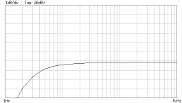
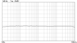
Did some measurements using Velleman PCSGU250 PCscope. Output loaded with 11ohm resistor. Looks pretty much linear from 10Hz to around 80KHz. Scope is an entry level measuring device, reading differences between 20Hz and 60KHz are smaller than scope accuracy error.
Attached are graphs and measure tables for 1Hz-1KHz and 10Hz-100KHz
It also sounds great
wb Margus

View attachment thewire1hz-1khz.txt

View attachment thewire10hz-100khz.txt
Did some measurements using Velleman PCSGU250 PCscope. Output loaded with 11ohm resistor. Looks pretty much linear from 10Hz to around 80KHz. Scope is an entry level measuring device, reading differences between 20Hz and 60KHz are smaller than scope accuracy error.
Attached are graphs and measure tables for 1Hz-1KHz and 10Hz-100KHz
It also sounds great
wb Margus

View attachment thewire1hz-1khz.txt

View attachment thewire10hz-100khz.txt
Andrew, you mean it would be good to use a low pass filter on input?
Owen, thank you! To be honest, i'm pretty proud of myself, back in the past usually my such projects ended up in smoke and sparks
About PSU-s, fets are running on PSU from old amp, toroidal transformer with two secondary windings, separate rectifier chains for each amp. For LME-s, separate transformer, regulators are tweaked Velleman kits http://www.velleman.eu/products/view/?id=8904 , for positive one only changed input cap, for neg one LM317 changed to LM337, diodes and caps in reverse polarity.
Will post some pics tomorrow.
wb Margus
Yes........ you mean it would be good to use a low pass filter on input? ..........
You may already have a passive RF filter on the input.
I cannot tell from the plot what RC you have fitted.
Last edited:
The Wire Amp for sale
As I will not have the time to finish my "The Wire Amp" build I have put my stereo kits (2x AMP PCB + 2x AMP Part Kits) and SMPS (2x DPS-600-55/65V (Reg LME)) up for sale in this thread.
Cheers,
Nic
As I will not have the time to finish my "The Wire Amp" build I have put my stereo kits (2x AMP PCB + 2x AMP Part Kits) and SMPS (2x DPS-600-55/65V (Reg LME)) up for sale in this thread.
Cheers,
Nic
@ NicMac, sorry to see that you wont be building The Wire, and that it has gone up for sale. Hopefully it will find another happy home.
Decided to stick with the dps-600's for my build. The alternative would either be mod'ing or building my own lower V supplies, which is just daft...
Seen a case by SiliconRay that I like, and I'm still milling over doing an adjustable bias circuit... and waiting to see what Owen's DAC is like...
Decided to stick with the dps-600's for my build. The alternative would either be mod'ing or building my own lower V supplies, which is just daft...
Seen a case by SiliconRay that I like, and I'm still milling over doing an adjustable bias circuit... and waiting to see what Owen's DAC is like...
@NicMac you may want to contact Gootee he was chasing some DPS600 a few weeks back over in this thread - http://www.diyaudio.com/forums/chip-amps/230482-lme49830-irfp240-9240-a.html#post3384463
Already contacted him!But thanks!
There's a slight snag: NicMac's power supplies might only work on 230 V mains.
Does anyone know if there are any reasonably-easy ways around that, so I could use them with 115 VAC?
Ohhh I had forgotten about that. All DPS600 models require 230V mains, there was DPS500 custom option discussed (to provide custom higher regulated voltage for the LME chip) but only Owen's prototype eventuated as there was never the quantity required for a GB on those. I don't have any solutions for the problem though unfortunately.
Already contacted him!But thanks!
There's a slight snag: NicMac's power supplies might only work on 230 V mains.
Does anyone know if there are any reasonably-easy ways around that, so I could use them with 115 VAC?
A simple external voltage doubler prior to the input of the DPS would do the trick. All you need is a few HV caps and some diodes to go from 120VAC to 360VDC, then just bypass the rectifier section of the DPS and feed the 360VDC straight onto the HV bus.
It's done all the time in SMPS to make for simple 120/240V compatibility, and I believe that's how it's done on the DPS500.
You might need to add an EMI filter before the voltage doubler
Cheers,
Owen
I think I could probably handle that. Thanks for pointing it out!
Of course, every home in the USA also has 230 V, since we get two phases. But the 230 V is almost always routed only to major appliances. And the only place there's usually a 230 V wall plug is at the clothes dryer.
Just thinking out loud, it might be possible for me to re-wire a dual 115V outlet, to have both phases (one on each plug). And then maybe I could make a box to combine them and have an outlet with two compatible 230V wall plugs. But it sounds like a voltage doubler circuit would be more foolproof (and obviously more broadly applicable, since I could then use it anywhere, here).
- Home
- Amplifiers
- Solid State
- "The Wire AMP" Class A/AB Power Amplifier based on the LME49830 with Lateral Mosfets